9 Anesthetic Gas Module Repairing the Anesthetic Gas Module
258
Top Cover PC Board
Removal
To remove the top cover PC board (refer to Figure 79 and Figure 80):
1 Ensure that the Module is switched off and isolated from the mains power supply. Remove the top
cover of the module.
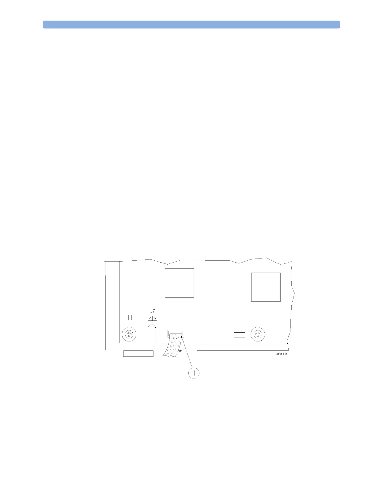
2 Remove the connector (1) from the top cover PC board.
3 Using a hex-socket screwdriver, remove the three nuts, washers and spacers (2) securing the PC
board to the top cover of the module.
4 Remove the PC board.
Replacement
To replace the top cover PC board (refer to Figure 79 and Figure 80):
1 Ensure that the Module is switched off and isolated from the mains power.
2 Carefully fit the PC board over the three locating screws on the top cover of the module.
3 Using a hex-socket screwdriver, replace the three nuts, washers and spacers (2) securing the PC
board to the top cover.
4 Replace the connector (1) to the top cover PC board.
5 Replace the top cover of the module.
Now perform the performance checks described “Test and Inspection Matrix” on page 262.
Figure 79 Removing the Top Cover PC Board Connection
 Loading...