9 Anesthetic Gas Module Introduction
174
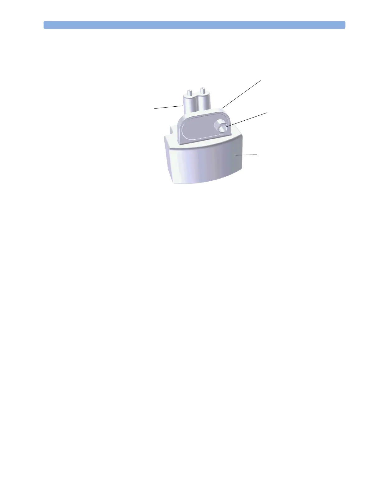
Watertrap
Figure 32 Watertrap
The watertrap consists of two water separation filters, two water fuses and a water reservoir. The gas
sample coming from the patient may contain fluids which are separated from the gas at the first water
separation filter. The gas is then split into two paths, the “measurement” path with the main part of the
total gas flow (including water vapor) continuing on the “dry” side of the separation filter and the
“drainage” path (containing any liquid droplets) with the smaller amount of the total flow continuing
on the “wet” side of this filter. At the pump both gas paths are recombined.
The watertrap proper includes “water fuses” in both the “measurement” and the “drainage” paths,
consisting of a material that swells when getting wet (when the reservoir is full or when fluid penetrates
the separation filter and enters the “measurement” path) and blocks the respective path at the inlet of
the unit. Once the “water fuses” are blown, any passage of fluid is blocked and the gas flow resistance
increases so that an occlusion is detected.
Sample Flow Through the Pneumatic Path
• The drainage path serves to withdraw fluid separated from the gas sample into the watertrap
reservoir, so that the AGM interior is protected from fluid that might cause an occlusion in the
measurement path.The drainage path leads into the large watertrap reservoir where all liquid water
and other fluids are collected. When the drainage path leaves the watertrap through a water
separation filter and a through a water fuse it leads through internal Nafion tubing then through a
bacterial protection filter and flow restrictor directly to the pump. This flow restrictor determines
the percentage distribution between drainage and measurement path flow.
• The measurement path leads through a water separation filter and through a water fuse on into the
measurement system. The patient sample gas (on the measurement path) then flows through
internal Nafion tubing and through a bacterial protection filter to the first solenoid valve. Room air
for the zero calibration is alternatively input (via a dust filter) to this solenoid valve. The solenoid
valve switches between the two gases depending on the current mode of operation - normal
measurement or zero calibration.
Patient Sample Inlet
Water Reservoir
Water Fuses
Water Separation Filters
 Loading...