Repairing the Anesthetic Gas Module 9 Anesthetic Gas Module
245
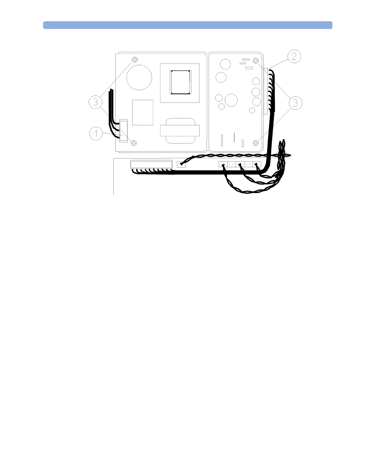
Figure 68 Removing and Replacing the Power Supply Unit
Main PC Board
Removal
To remove the main PC board (refer to Figure 69):
1 Ensure that the Module is switched off and isolated from the mains power supply. Remove the top
cover of the module.
2 Remove the pneumatics tubing from the pressure transducer (1).
3 Remove the main PC board connector (2) from the power supply unit.
4 Remove the power connectors (3) that connect the main PC board to the fan, solenoid valve #1,
pump and solenoid valve #2.
5 Remove the flat-cable connector (4) from the IR measurement head.
6 Remove the flat-cable connector (5) from the RS232 connector.
7 Remove the flat-cable connector (6) from the agent identification head.
8 If O
2
sensor is present, remove the flat-cable connector (7) from the small O
2
sensor PC board (or
directly from the O
2
sensor, for sensors with integrated PC board).
9 Remove the connector (9) from the power LED.
10 Using a cross-tipped screwdriver, remove the cable clamps (12).
11 Using a cross-tipped screwdriver, remove the 6 screws (10) securing the main PC board to its
mounting on the module.
12 Carefully remove the main PC board.
 Loading...