Troubleshooting the Anesthetic Gas Module 9 Anesthetic Gas Module
215
Diagnostic Checks
WARNING If you carry out checks with replacement parts, be aware of the high-voltage locations. Never remove
cables or sub-assemblies while the Module is powered on.
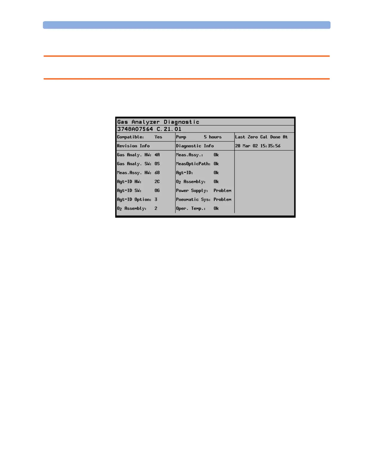
To access the Gas Analyzer Diagnostic window select Gas Analyzer Diagnostic in the Setup
Gas Analyzer
menu.
Figure 50 Gas Analyzer Diagnostic Window
Problem Solving Hierarchy
To help identify a problem, a OK/Problem message is displayed for major subassemblies. If a
problem is displayed use the following pages to isolate the problem according to the following
hierarchy (this hierarchy overrides the sequence shown on the display):
1 Pneumatic System
2 IR Measurement Assembly (Meas. Assy)
3 Optical Path (Meas. Optic. Path)
4 O
2
Assembly (O
2
Assy)
5 Agent ID Assembly (Agt-Id Assy)
6 Power Supply
7 Operating Temperature
The
Gas Analyzer Diagnostic window also displays the number of pump operation hours.
NOTE To remove the top cover, refer to the section The Top Cover.
Refer to the following tables for possible causes of
Problem indications, and their recommended
corrective actions.
 Loading...