Checking and Calibrating the Anesthetic Gas Module 9 Anesthetic Gas Module
191
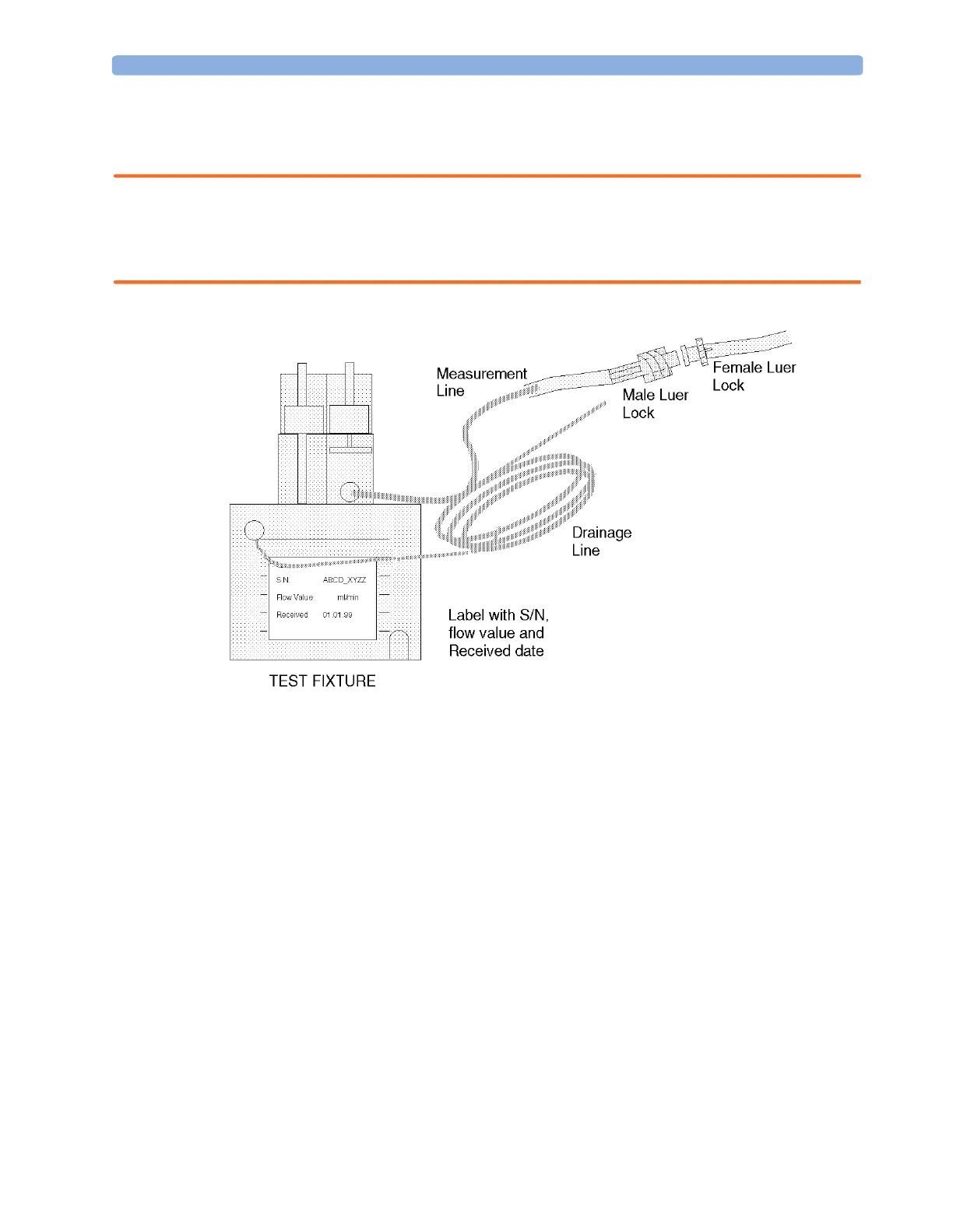
while performing the leakage check. Block the measurement line with a luer cap or a similar device
and the drainage line with your fingertip. If a leak exists, replace the test fixture.
WARNING Always handle the test fixture carefully and avoid contact with dust. Do not change or modify the test
line/loops as this can change the flow resistance.
Make sure that there are no sharp bends or kinks in the tubing that leads to the test fixture. If a kink is
visible, replace the fixture and use the new one.
To make the flowrate measurements and any necessary adjustment:
1 Enter the service mode of the monitor and let the Philips M1026A Anesthetic Gas Module
complete the warm-up phase (the
GA WARMUP INOP disapears).
2 In the Setup Gas Analyzer menu select Service Window then select Calibration to
access the
Gas Analyzer Calibration window.
3 Enter the Setup Gas Analyzer menu and select Start Flow Cal.
4 Select Flow Rate.
5 Select Normalfor normal flow (150 ml/min).
6 Remove the watertrap from its manifold and connect the flow split test fixture to the Philips
M1026A Anesthetic Gas Module.
7 Connect the measurement line of the test fixture to the flowmeter using the mal Luer Lock.
Check 8 Note the actual flowrate by following the instructions accompanying the flowmeter. If the actual
flowrate is outside the tolerance, it must be adjusted. The target value for the flow is labelled on the
test-fixture. If no adjustments are required, select
Stop Flow Cal.
xxx
 Loading...