Home
Phoenix Contact
Controller
RFC 4072S
Phoenix Contact RFC 4072S User Manual
4
of 1
of 1 rating
272 pages
Give review
Manual
Specs
To Next Page
To Next Page
To Previous Page
To Previous Page
Loading...
RFC
4072S
202 / 272
PHOENIX CONTACT
108580_en_02
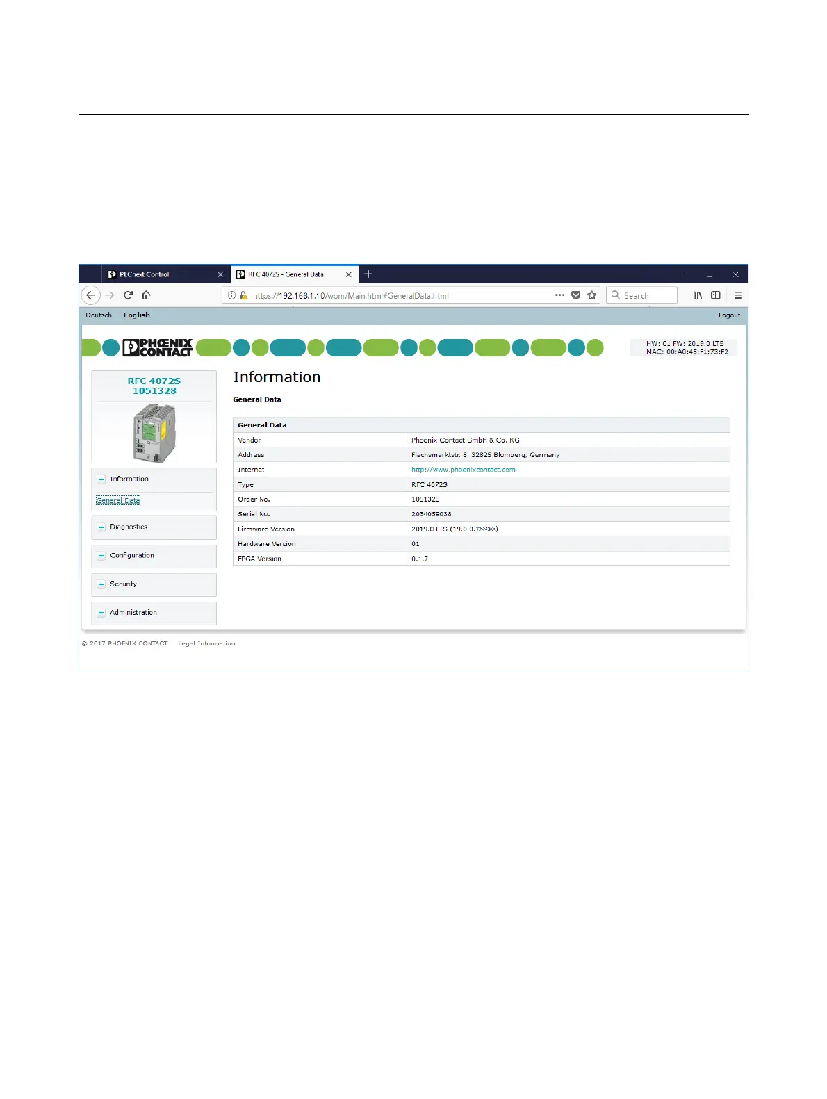
9.6.1
“Information” area
This area includes general device information.
9.6.1.1
“Genera
l Data
” page
Here you will find general details on the devi
ce, e.g., device version and order number as
well as manufacturer details.
Figure
9-6
WBM: “General Data” page
201
203
Table of Contents
Table of Contents
3
1 For Your Safety
9
Identification of Warning Notes
9
Qualification of Users
9
Information about this User Manual
10
Purpose of this User Manual
10
Validity of the User Manual
10
Licensing Information on Open Source Software
10
Requesting the Source Code
11
General Safety Notes
12
Product Changes
14
Unauthorized Network Access
14
Electrical Safety
15
Safety of the Machine or System
16
Standards and Directives
17
Intended Use
18
Documentation
19
System Requirements (Hardware and Software)
20
Disposal
20
Abbreviations Used
21
Safety Hotline
21
2 Description of the RFC 4072S
23
General Description of the RFC
23
Safety-Related Mode of Operation of the RFC 4072S
25
Profisafe: Management/Diagnostic Variables for Communication Diagnostics
26
Calculating/Determining the Response Time
28
(Safety Function Response Time, SFRT)
28
*) = Not Necessarily the Output Device
29
Calculation of the SFRT Response Time
29
Max
29
Max /F_Wd_Time out
30
Appendix For Document Lists
30
*) = Not Necessarily the Output Device
30
Simplified Calculation of the SFRT Response Time
30
Determining F_Wd_Time in
32
Min
32
AXL F BK PN TPS PROFINET Bus Coupler)
33
Settings" Editor of the Interface Editor Group of the PROFINET Device
33
Min /F_Wd_Time out
32
Plcnext Engineer: "Safety Cockpit" Editor in the Editor Group of the "Safety PLC
35
RFC 4072S Display: Cycle and Program Runtime of the Ispns 3000 (B)
35
Determining F_Wd_Time In/F_Wd_Time out to be Parameterized and Checking/Validating that the Safety Function Can be Implemented
38
Indicators, Interfaces, and Operating Elements
39
Figure 2-29: Mode Selector Switch
39
Structure of the RFC 4072S Remote Field Controller Including Fan Module
39
Security Seal and Test Mark
40
Fan Module
41
Status and Diagnostics Indicators (Ethernet)
42
Touch Screen Display
42
LNK and ACT Leds
42
Structure of the Display (Diagnostic Display)
44
Plcnext DETAILS" Menu (Standard Controller)
44
Structure of the Display
44
Indicators on the Display
45
Status Information
45
Status Information: Plcnext (Standard Controller)
45
Status Information: Safety PLC (Ispns 3000)
46
Status Information: OPC UA (OPC UA Server)
47
Status Information: PN Control (PROFINET Controller)
47
Status Information: PN Device (PROFINET Device)
48
Diagnostic Indicators in the Home Menu (Leds)
49
Diagnostics Indicators
49
Safety PLC (Safety-Related PROFINET Controller Ispns 3000)
49
Diagnostic Indicators: PN Control (PROFINET Controller)
50
Home Menu
51
CONFIG DETAILS" Menu
52
Plcnext DETAILS" Menu (Standard Controller)
53
Plcnext DETAILS" Menu (Safety-Related PROFINET Controller)
54
S-PLC DETAILS" Menu (Ispns 3000)
54
S-PLC DETAILS" Menu: Submenus
54
OPC UA DETAILS" Menu (OPC UA Server)
55
Figure 2-24 "PN-C DETAILS" Menu (PROFINET Controller)
56
Figure 2-25 "PN-D DETAILS" Menu (PROFINET Device)
56
PN-C DETAILS" Menu (PROFINET Controller)
56
PN-D DETAILS" Menu (PROFINET Device)
56
Figure 2-26 USB Interface of the RFC 4072S
57
USB Interface (Currently Not Supported)
57
Figure 2-27: Interfaces of the RFC 4072S
58
Ethernet Connection
59
Connection Example of the Ethernet Interfaces
60
Figure 2-28 PROFINET Example Installation
60
Interfaces
58
Mode Selector Switch
61
Power Supply
62
Sizing of the Power Supply
62
Figure 2-30 Overload Range with Fall-Back Characteristic Curve
63
Figure 2-31 Overload Range Without Fall-Back Characteristic Curve
63
Directory Structure of the File System
64
Figure 2-32 Administrator Password on the Controller
67
Firewall
67
Using SFTP to Access the File System
67
3 Mounting, Removal, Electrical Installation, and Replacement
69
Safety Notes for Mounting and Removal
69
Mounting the RFC FAN MODULE Fan Module
71
Figure 3-1 Mounting the RFC FAN MODULE Fan Module
71
Mounting the RFC 4072S
72
Figure 3-2 Mounting the RFC 4072S
72
Removing the RFC 4072S
73
Inserting/Removing the SD Card (Parameterization Memory)
73
Figure 3-3 Mounted RFC 4072S with End Brackets and Maximum Distance between the DIN Rail Fastening Points (160 MM)
73
Inserting/Removing the USB Memory Stick
74
Figure 3-4: Inserting (A) or Removing (B) the SD Card (Parameterization Memory)
74
Connecting the Interfaces
75
Connecting an Ethernet Network
75
Figure 3-5 Cabling between an Ethernet Network and the RFC 4072S
75
Connecting the Supply Voltage
76
Figure 3-6 Connecting the Supply Voltage
76
Replacing the RFC 4072S
77
Figure 3-7 Removing the Power Supply
77
Figure 3-8 Disconnecting the Ethernet Connection
78
Figure 3-9 Removing the RFC from the DIN Rail
78
Figure 3-10 Removing the Fan Module
79
Figure 3-11 Mounting the RFC FAN MODULE Fan Module
80
Figure 3-12 Snapping the RFC Onto the DIN Rail
80
Figure 3-13 Establishing the Ethernet Connection
81
Figure 3-14 Connecting the Power Supply
81
4 Startup and Validation
83
Initial Startup
83
Steps for Initial Startup of the RFC 4072S
83
Figure 4-53: Safety-Related Example Program
85
Figure 4-6: Defining a Project Password
85
Restart after Replacing the RFC 4072S
86
Steps for Restarting the RFC 4072S
87
Example Startup of the RFC 4072S
88
Example of a Profinet/Profisafe Configuration with
88
Figure 4-1 Example Configuration
88
PROFINET Controller/F-Host
88
Integration of the RFC 4072S in Plcnext Engineer as a PROFINET Controller
89
Software Requirements
90
Installing Plcnext Engineer
90
Plcnext Engineer Licenses
90
Plcnext Engineer Software
90
Figure 4-2: Plcnext Engineer User Interface
91
User Interface
91
Creating a New Project
92
Figure 4-3 Start Page, "Empty RFC 4072S Project" Project Template
92
Configuring the Controller IP Settings
93
General Information
93
Important Information
93
Figure 4-4 Setting the IP Address Range
94
Setting the IP Address Range
94
Figure 4-5 Setting the IP Address
95
Setting the IP Address
95
Defining a Project Password
96
Connecting to the Controller
97
Figure 4-7 Selecting the Network Card
97
Figure 4-8 Assigning Online Devices
97
Figure 4-9 Successful Assignment of the Configured Controller to an Online Device
98
Figure 4-10 User Authentication: Entering a User Name and Password
99
Figure 4-11 Successful Connection to the Controller
99
Configuring PROFINET Devices
100
Adding PROFINET Devices
100
Figure 4-12 Role Picker for Selecting PROFINET Devices
100
Figure 4-13: PROFINET Devices in the "PLANT" Area and in the Device List
100
Assigning Online Devices (Device Naming)
101
Figure 4-14 Selecting the Network Card
101
Figure 4-15 Assigning Online Devices
101
Adding I/O Modules
102
Figure 4-16 Successful Assignment of the Configured PROFINET Devices to an Online Device
102
Figure 4-17 Role Picker for Selecting I/O Modules
103
Figure 4-18 Entering the Project Password
103
Figure 4-19: Successful Login to the Safety-Related Area
104
Figure 4-20: I/O Modules of a PROFINET Device in the "PLANT" Area and in the Module List
104
Figure 4-21 Reading I/O Modules of a PROFINET Device Automatically
105
Figure 4-22 Axioline F Modules in the Example Project
105
Programming in Accordance with IEC 61131-3 - Non-Safety-Related Example Program
106
Figure 4-23: Selecting the Programming Language for the First Worksheet
106
Opening and Creating the POU
106
Figure 4-24: "Add Program" Context Menu
107
Creating Variables
108
Figure 4-25: Creating Variables for a POU (in the Example: for the "Main" POU)
108
Figure 4-51: Creating Variables for a POU
108
Input/Output Variables in the Example (Logical Anding)
108
Creating a Program
109
Figure 4-26: Example Program in FBD
109
Figure 4-27: Adding a Code Worksheet to a POU
109
Instantiating a Program
110
Figure 4-28: Tasks and Program Instances in the "Tasks and Events" Editor
110
Assigning Process Data
111
Figure 4-29 Example: List of All Available Variables Plcnext Engineer
111
For Programs in Accordance with IEC 61131-3
111
Without in and out Ports
111
Figure 4-30 Role Picker for Selecting Process Data
112
Figure 4-31 Selected Process Data Item
112
Figure 4-32: Example: List of All Available Process Data Items
113
Figure 4-33: Role Picker for Selecting Variables
113
Figure 4-34 Selected Variable
114
Figure 4-35 Example: List of All Available in and out Ports
114
For Programs in Accordance with IEC 61131-3 with in and out Ports
114
Figure 4-36: Role Picker for Selecting in Ports
115
Figure 4-37: Role Picker for Selecting out Ports
115
Transferring a Project to the Controller
116
Figure 4-38 Controller in the RUN State, PROFINET Controller in the ACTIVE State
116
Displaying Online Values
117
Figure 4-39 "Variables" Editor: Online Values of the Variables Used
117
Figure 4-40 "Code" Editor: Online Values of the Variables Used
117
Creating a Plcnext Engineer HMI Application
118
Programming in Accordance with IEC 61131-3 - Safety-Related Example Program
119
Assigning/Checking the Profisafe Address (F-Address) of Profisafe Devices
119
Figure 4-41: F-Address of the F-Host: F_Source_Add (F_Source_Address)
119
Figure 4-42: F-Address of the Profisafe F-Device: F_Dest_Add (F_Destination_Address)
120
Management/Diagnostic Variables for F-Devices
121
Figure 4-44 Management/Diagnostic Variables for All Configured F-Devices
122
Figure 4-45 Management/Diagnostic Variables of F-Devices (Default)
122
Checking/Setting Safety Parameters for Configured F-Devices
123
Figure 4-46 "Safety Parameters" Editor: AXL F PSDI8/4 1F
123
Figure 4-47 "Safety Parameters" Editor: AXL F PSDO8/3 1F
124
Creating Variables (Exchange Variables)
125
Figure 4-48 Exchange Variables in the Example
125
Figure 4-49: "Add Variable (Safety PLC)" Context Menu
126
Figure 4-50 Setting the Data Direction
127
Opening a Safety-Related POU
127
Creating Variables
128
Input/Output Variables in the Example (Safe Logical Anding)
128
Creating a Safety-Related Program
129
Figure 4-52 Selecting Diagnostic/Management Variables
129
Assigning Process Data
131
Figure 4-54 Assigned Safety-Related Process Data
131
Transferring a Project to the Controller
132
Figure 4-55 Standard Controller in the RUN State
132
Transferring a Non-Safety-Related Project to the Standard Controller
132
Figure 4-56 Standard Controller in the "RUN" State
133
Figure 4-57: Controller Password: Entering the Password for the Safety-Related Controller
134
Transferring a Safety-Related Project to the Safety-Related Controller (Defining a Controller Password, if Necessary)
134
Figure 4-58: Information Dialog: Prevent any Hazard Posed by the Safety-Related Controller Being Started and Stopped
135
Figure 4-59 Safety-Related Controller in the RUN State
135
Figure 4-60 Safety Cockpit: Safety-Related Controller in the "RUN" State - Safe Run
136
Figure 4-61 "Variables" Editor (S_Main): Online Values of the Variables Used
137
Figure 4-62 "Code" Editor (S_Main): Online Values of the Variables Used
138
Figure 4-63 Exiting Safe Mode - Switching to Debug Mode
139
Figure 4-64 Display: Debug Mode Indicated
139
Figure 4-65 Exiting Debug Mode - Switching to Safe Mode
140
Figure 4-66 Plcnext Engineer - Passivated Profisafe F-Devices
141
Figure 5-1 Asyncom_Pn_1 Function Block
152
Figure 5-2 Function Block Pnfd_Axl_Diag_1
153
Figure 6-1 Replacing the RFC FAN MODULE Fan Module
156
Figure 6-2 Standard Controller in the "STOP" State
158
Overview of the Function Blocks
172
Diagnostic Status Register of the Ispns 3000
176
SPNS System Variable and Elements of the SPNSV2_TYPE Structure
176
Spns.diag.status_Reg
180
Contents of Bits 5 and 6 and Corresponding LED Indicators
181
SPNS_V2_PROFISAFE_DIAG System Variable and Elements of the PROFISAFE_DIAG_OUT Structure
182
Figure 4-43: Management/Diagnostic Variables for each Configured F-Device
183
Management/Diagnostic Variables for each Configured F-Device
184
Management/Diagnostic Variables for F-Devices
187
PROFINET System Variables (PROFINET Controller Functionality)
189
PROFINET System Variables (PROFINET Device Functions)
190
System Variables for the TCP_SOCKET, UDP_SOCKET, and
191
DEVICE_STATE System Variable and Elements of the Device_State_4Xxx_Type Structure
192
ESM_DATA System Variable for Task Handling and Elements of the ESM_DAT Structure
192
HMI_CONTROL System Variable and Elements of the HMI_CONTROL_TYPE Structure
194
HMI_STATUS System Variable and Elements of the HMI_STATUS_TYPE Structure
194
User Roles and Their Assigned Access Permissions in the Various Applications
210
Shell Commands for Controlling the Firmware
235
Contact Assignment of the USB 3.0 Interface (Type A)
237
Contact Assignment of the Ethernet Interfaces Depending on
239
Appendix A
235
D Appendix For Document Lists
255
D 2 List of Tables Section 1 Section 2
261
4
Based on 1 rating
Ask a question
Give review
Questions and Answers:
Need help?
Do you have a question about the Phoenix Contact RFC 4072S and is the answer not in the manual?
Ask a question
Phoenix Contact RFC 4072S Specifications
General
Brand
Phoenix Contact
Model
RFC 4072S
Category
Controller
Language
English
Related product manuals
Phoenix Contact INTERBUS
82 pages
Phoenix Contact AXC F 1152
113 pages
Phoenix Contact AXC F 3152
113 pages
Phoenix Contact ILC 150 ETH
78 pages
Phoenix Contact IBS ABB DSC-T
118 pages
Phoenix Contact ILC 191 ME/AN
168 pages
PLCnext AXC F 2152
9 pages
ELR W3 500AC I Series
56 pages
EV Charge Control Basic
70 pages
ELR H5-IES-SC-24DC/500AC-2
56 pages
ELR H5-IES-SC-24DC/500AC-9
56 pages
ELR H5-IES-SC-24DC/500AC-0,6
56 pages