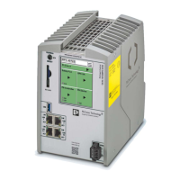
RFC 4072S
256 / 272 PHOENIX CONTACT 108580_en_02
Figure 2-24: “PN-C DETAILS” menu (PROFINET controller) .................................. 56
Figure 2-25: “PN-D DETAILS” menu (PROFINET device) ...................................... 56
Figure 2-26: USB interface of the RFC 4072S ........................................................ 57
Figure 2-27: Interfaces of the RFC 4072S ............................................................... 58
Figure 2-28: PROFINET example installation ......................................................... 60
Figure 2-29: Mode selector switch .......................................................................... 61
Figure 2-30: Overload range with fall-back characteristic curve ..............................63
Figure 2-31: Overload range without fall-back characteristic curve ......................... 63
Figure 2-32: Administrator password on the controller ............................................67
Section 3
Figure 3-1: Mounting the RFC FAN MODULE fan module .................................... 71
Figure 3-2: Mounting the RFC 4072S ................................................................... 72
Figure 3-3: Mounted RFC 4072S with end brackets and maximum distance
between the DIN rail fastening points (160 mm) ................................. 73
Figure 3-4: Inserting (A) or removing (B) the SD card (parameterization memory) 74
Figure 3-5: Cabling between an Ethernet network and the RFC 4072S ................ 75
Figure 3-6: Connecting the supply voltage ............................................................ 76
Figure 3-7: Removing the power supply ................................................................77
Figure 3-8: Disconnecting the Ethernet connection .............................................. 78
Figure 3-9: Removing the RFC from the DIN rail ................................................... 78
Figure 3-10: Removing the fan module ................................................................... 79
Figure 3-11: Mounting the RFC FAN MODULE fan module ....................................80
Figure 3-12: Snapping the RFC onto the DIN rail ....................................................80
Figure 3-13: Establishing the Ethernet connection ..................................................81
Figure 3-14: Connecting the power supply .............................................................81
Section 4
Figure 4-1: Example configuration ........................................................................ 88
Figure 4-2: PLCnext Engineer user interface ........................................................ 91
Figure 4-3: Start page, “Empty RFC 4072S project” project template ...................92
Figure 4-4: Setting the IP address range ...............................................................94
Figure 4-5: Setting the IP address ......................................................................... 95
Figure 4-6: Defining a project password ...............................................................96
Figure 4-7: Selecting the network card .................................................................. 97
Figure 4-8: Assigning online devices .................................................................... 97

 Loading...


