Radioddity Extended manual for Radioddity DB25-D, DB40-D & GD-88 v3.0
© Radioddity 2023 page 188 of 252
13.26.6 Crossband digital to digital
Input channel: Set one channel for Ch Mode ‘A&D, TX-D’ and set it for Relay
mode ‘Only RX’ or ‘Rx and TX’. The frequency specified for RX
will be used for either cross repeating the digital signal
received. Only those digital signals will be repeated that match
the settings for RX TS and RX CC.
Output channel: Set another channel for Ch Mode ‘Digital’ and the required
settings for TX TS and TX CC.
Operation: Select one of those two channels for VFO A and select the
other channel as VFO B. The analog or digital signal as
received on the selected input channel will be repeated on the
selected output channel.
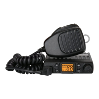
Sample settings (only relevant parts shown):
The Radioddity DB40-D/GD-88 will receive digital on VFO-A (144.100 MHz), CC 1,
TS 1 and digital transmit the received signal on VFO-B (433.100 MHz) with the CC,
TS and Contact as specified acting as a digital to digital crossband-repeater.
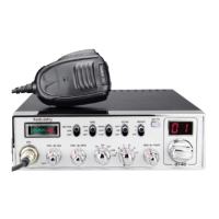
The DMR ID of the received station will be
shown on the left of the receiving VFO.
Depending on the use of DMR ID Data and/or
Talker Alias, additional details may be shown.
The transmitted DMR ID will be shown on the
left of the transmitting VFO.
Notes: If no contact has been selected for the digital output channel, repeating will
fail and a message, stating ‘No Contact’ will be displayed on the radio screen.
If no contact has been selected for the digital output channel, repeating will
fail and a message, stating ‘No Contact’ will be displayed on the radio screen.
If ‘Relay Monitor’ is turned on for the input channel, only those signals will be
monitored that do match the RX-group settings.
Do not forget to activate Repeater-Mode as described in chapter 10.6 Local
Set - ABRepeat on page 92. The upper display line should state ‘A->B’.