Measurement Setup
R&S
®
TSMA6
74User Manual 4900.8057.02 ─ 11
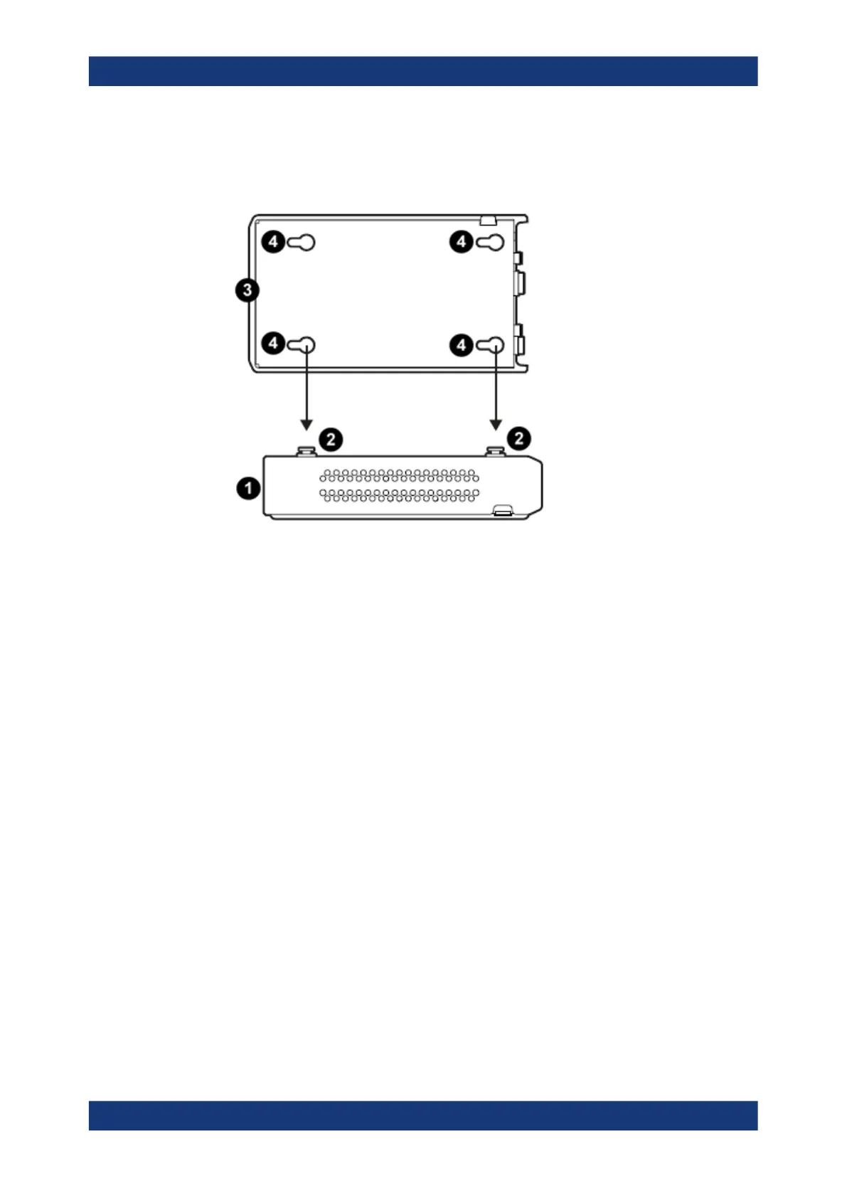
3. Align the collars with the snap-in holes on the bottom of the additional devices and
press these devices down.
Figure 7-14: Aligning R&S TSME6/TSMExxDCs
1 = 1st R&S TSME6/TSMExxDC
2 = Collar screws
3 = 2nd R&S TSME6/TSMExxDC
= Snap-in holes on the bottom pane of R&S TSME6/TSMExxDC
4. Connect DC power cable R&S TSMA6-BPP1 resp. R&S TSMA6-BP2T from
AUX1 / AUX2 to the DC IN socket of the devices (seeFigure 7-12 ).
Vibration-proofed stacking