Page 141
STAT
IM
2000/2000S Service Guide
96-108639 Rev 3.0
7. Electrical and Electronic Components
Electrical and Electronic
Components
Controller Board
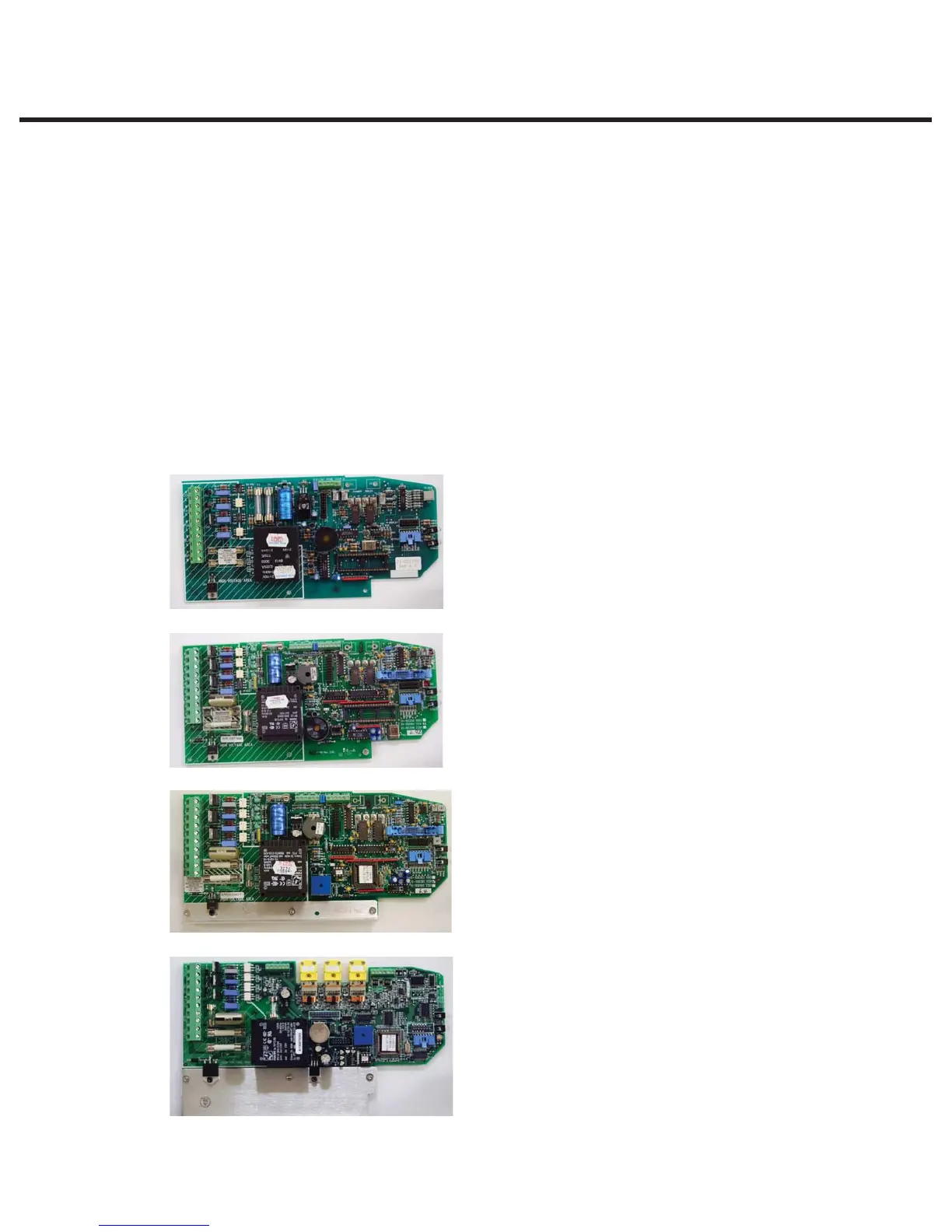
Identifying the Controller Board Type
There are different types of controller boards which may be encountered while servicing STAT
IM
2000/2000S type units (see ‘PCB revision’ chart in Chapter 1. Identifying Your STATIM). They can
be identified as below (Figure 1):
Typical features:
t Revision number bottom right hand side
t Single, rectangular microprocessor
Typical features:
t Revision number bottom right hand side
t Rectangular microprocessor plus EPROM
t ‘W1’ jumper for calibration
t Blue ‘pressure interface/printer’ connector
Typical features:
t Revision number bottom right hand side
t Square microprocessor plus EPROM
t ‘W1’ jumper for calibration
t Blue ‘pressure interface/printer’ connector
Typical features:
t Up to revision 7.30 the revision number is on the top
right hand side printed vertically
t From revision 7.40 onwards, the revision number is
on the bottom left hand side (printed horizontally)
under the connector J1
t Square microprocessor plus EPROM
t NO ‘W1’ jumper for calibration
t NO Blue ‘pressure interface/printer’ connector
t All components integrated on single board.
t Surface mount type component.
t ‘Push In’ yellow thermocouple connectors
Revision 3.x/4.x type board (1992 — 1995):
Revision 2.x/5.x type board (1995 —2004):
Revision 6.x type board (2004 —2007):
Revision 7.x type board (2007 to present):
Figure 1
STATIM 2000/2000S/2000 G4 Service Guide