Page 180
STAT
IM
2000/2000S Service Guide
96-108639 Rev 3.0
8. Water Pumps, Reservoir, and Compressor
Removing the SciCan or Ulka Pump Assembly
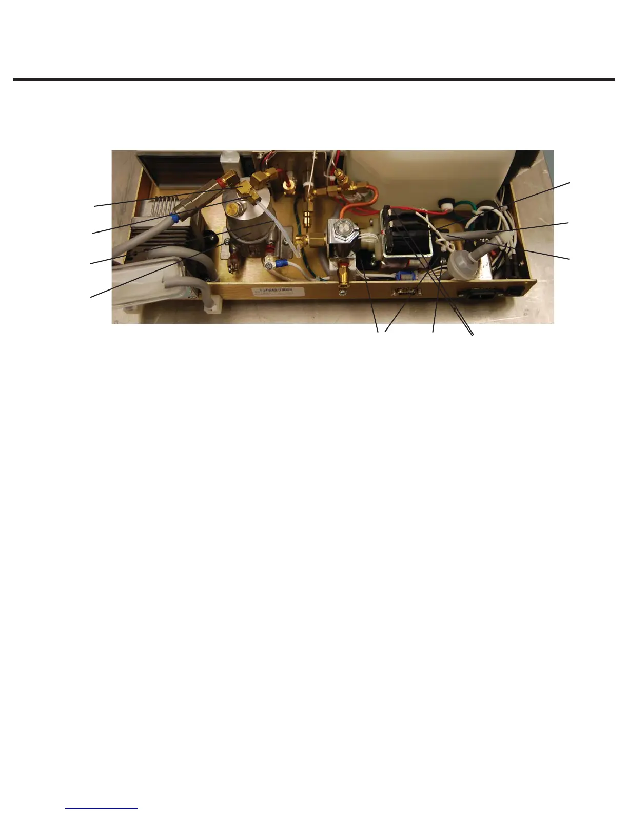
To remove the pump assembly, proceed as follows (see Figure 16):
1. Cut and remove the cable tie (1) holding the inlet tube (2) to the pump inlet fitting (3). Do not
nick the tubing while cutting the cable tie. Remove the rubber tube from the inlet fitting and
clamp or stop the end of the tube securely.
2. Using a 3/8-inch wrench, remove the compression nut (4) attached to the Teflon™ tube (5),
from the inlet fitting (6) on the top of the steam generator (7).
3. Disconnect the appropriate terminal connectors (8) from the pump. Note the position of each
terminal before removal.
4. The pump assembly is secured to the chassis by rubber brackets (9) and four shoulder
screws (10). Remove the four shoulder screws and retain for re-assembly. Remove the pump
assembly from the chassis.
Reinstalling the SciCan or Ulka Pump Assembly
To reinstall the pump assembly, proceed as follows (see Figure 5):
1. Slide the outlet side of the pump under the solenoid valve bracket and place the pump onto
the chassis. Position the rubber brackets (9) so that the mounting holes align with the threaded
holes in the chassis. Secure the four shoulder screws (10) using Locktite® Threadlock Perma-
lock compound LM113 or equivalent. Do not kink the Teflon™ tube.
2. Push the open end of the rubber pump inlet tube (2) extending from the water reservoir on to
the pump inlet fitting (3) as far as it will go. Secure the tube to the fitting using a cable tie (1).
3. Thread the compression nut (4) on the Teflon™ tube (5) to the inlet fitting (6) on top of the
steam generator (7) until finger tight then tighten this nut using a 3/8-inch wrench. Do not
overtighten.
4. Connect the appropriate terminal connectors (8) to the pump.
Figure 16(Ulka Pump shown)
1
2
3
8109
7
5
4
6
1. Cable tie
2. Inlet tube
3. Pump inlet fitting
4. Compression nut
5. Teflon tube
6. Inlet fitting
7. Steam generator
8. Terminal connectors
9. Rubber brackets
10. Screws
STATIM 2000/2000S/2000 G4 Service Guide