Page 182
STAT
IM
2000/2000S Service Guide
96-108639 Rev 3.0
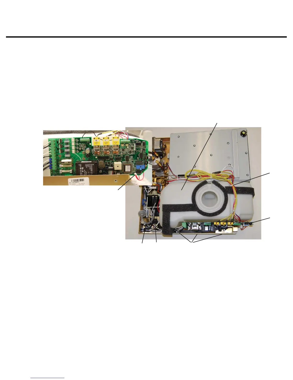
8. Water Pumps, Reservoir, and Compressor
1. Drain the reservoir.
2. Cut the appropriate cable ties (4) to release the wiring so that it does not restrict the removal of the
reservoir, and remove the appropriate sensor leads from the controller board terminal positions.
NOTE: The terminal positions on the controller board so that the sensors may be
re-connected correctly. This will vary depending on the controller type.
3. Cut the cable tie (4) securing the reservoir supply tube (5) to the pump fitting (6) and remove
the tube from the fitting.
4. Tilt the unit on its side so that the reservoir and PCB are at the top of the unit. Locate and
remove three nylon cap nuts with washers (7) on the bottom of the chassis securing the
reservoir. Retain the cap nuts and washers.
5. Place the unit back on its feet and carefully remove the reservoir from the chassis. BE
CAREFUL NOT TO DAMAGE THERMOCOUPLE LEADS.
Reinstalling the reservoir
To reinstall the reservoir, proceed as follows (see Figure 18):
1. Carefully place the reservoir (1) in the chassis taking care not to damage the wiring.
2. Tilt the unit on its side so that the reservoir and PCB are at the top of the unit. Locate and
install the three nylon cap nuts with washers (7) on the bottom of the chassis securing the
reservoir.
3. Place the unit back on its feet.
4. Connect reservoir supply tube to pump fitting and secure with cable tie.
5. Reconnect the appropriate sensor leads from the controller board terminal positions.
6. Using cable ties, fasten the leads back in their original positions.
7. Fill the reservoir with steam-process distilled water.
Note: if filling the reservoir before re-connecting the sensor leads, touch the leads to an
earthed point to discharge any static electric charge that may have built up on the reservoir.
This reduces the chance of ESD damage to the controller board.
1. Reservoir
2.
a. Float sensor leads
b. Conductivity sensor leads
3. Controller board
4. Cable tie
5. Reservoir supply tube
6. Pump fitting
7. Nylon cap nuts with washers
(not shown)
1
5 6 7 (under chassis)
3
4
2
Figure 18
STATIM 2000/2000S/2000 G4 Service Guide