Page 189
STAT
IM
2000/2000S Service Guide
96-108639 Rev 3.0
8. Water Pumps, Reservoir, and Compressor
STATIM 2000/2000S/2000 G4 Service Guide
Compressor
Most STAT
IM
2000 type units have been manufactured with a compressor that forces air through
the steam generator and cassette to remove residual moisture and to dry the instruments.
Air is drawn into the compressor (where fitted) through a circular foam air filter located behind a
cover plate on the rear of the compressor. This plate can be accessed from the rear of the unit
with the cover still attached. The air is then directed through a bacteria-retentive air filter (where
fitted) which is held in a bracket attached to the rear cover of the unit.
Details on changing these filters can be found in Chapter 2,
Tools, Maintenance Schedules,
Procedures and Testing.
Note: To test the compressor the control box should be attached to the unit or ‘compressor’
selected in the device test sub menu of the revision 7.x controller board service menu (if cover
is removed but still connected).
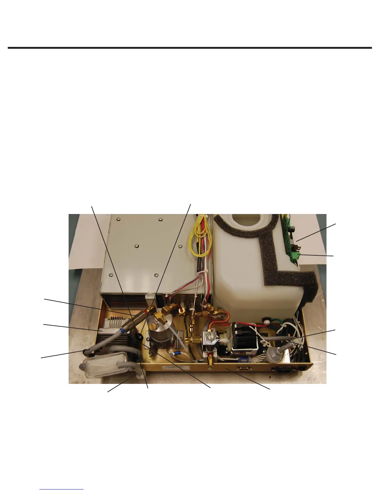
Figure 24
11
9
8
13
12
3
2
1
57
4
6
10
1. Silicone tube
2. Compressor
3. Setam generator check valve
4. Cable tie
5. Silicone tube
6. Chassis
7. Filter fitting
8. Compressor leads
9. Controller board
10. Screws (partially obscured)
11. Rubber mount
12. Ground wire (obscured)
13. Ground post (obscured)