Page 149
STAT
IM
2000/2000S Service Guide
96-108639 Rev 3.0
7. Electrical and Electronic Components
STATIM 2000/2000S/2000 G4 Service Guide
STAT
IM
2000 G4 Electronics
Removing and Replacing the STAT
IM
2000 G4 LCD Controller Board
NOTE: After replacing the LCD controller board, the bubble level must be calibrated.
Follow bubble level calibration instructions below.
To remove the LCD controller board, remove the cover to access the inside of the fascia
(see Figure 12).
1. Disconnect the LCD controller board (1) from the P3 connection on the main controller board
and disconnect the LCD’s DC power source cable (2) from the DC power source (3) located at
the back of the unit.
2. Place the cover upside down on a work surface and disconnect the flexible PCB connector (4)
cable connecting the colour LCD to the LCD controller board. To do this, slide your fingernail
into the centre of the hinged catch (5) and pull away from the board. Once open, the hinge will
release the connector.
3. To remove the LCD controller board, start by freeing it from the bottom and right clips (6) and
lift it out. Remove the cable ferrites from the holding clamps.
4. Disconnect the USB cable (7).
5. Disconnect the Ethernet port cable (8).
6. Disconnect the wires to the speaker (9).
To replace the colour LCD controller board, follow these steps (see Figure 5).
1. Re-connect the wires to the speaker (9).
2. Re-connect the Ethernet port cable (8).
3. Re-connect the USB cable (7).
4. Clip the logic board back into position. NOTE: Be certain the board is properly clipped into
position. An improperly seated board will affect the functioning of the level.
5. Connect the flexible PCB connector, pushing it down into position and closing the hinged
connector. Give the flexible PCB connector a gentle tug to ensure it is properly held in
position.
6. Connect the LCD controller board to the P3 connection on the main controller board, connect
the LCD DC power cable to the DC power source and plug in the unit.
7. Power ON the unit to test the colour LCD touchscreen
To calibrate the bubble level, proceed as follows:
1. Set the unit on a flat surface. Use a bubble level placed on the cover of the unit to ensure the
unit is level.
2. Access the service menu as described in Chapter 3 in the section titled Using the service
menu on the STATIM G4.
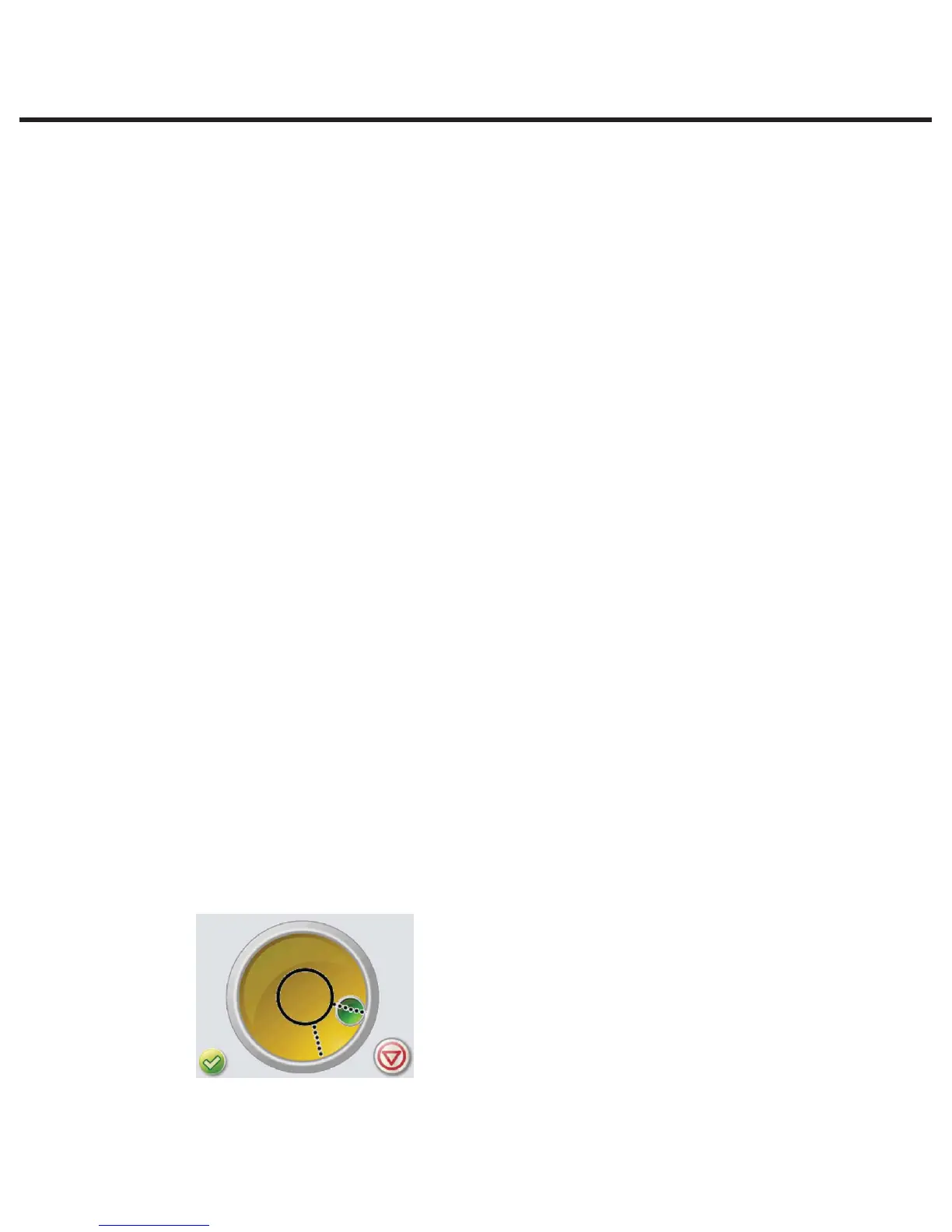
3. Scroll to the Bubble level calibration screen.
4. Press the check mark until the bubble is properly centered in the middle of the circle (wait a
few seconds after pressing to allow it to reset).
5. When the bubble stays within the screen’s center circle, the bubble level is calibrated.
Press STOP to exit.