Page 242
STAT
IM
2000/2000S Service Guide
96-108639 Rev 3.0
12. Printer and Data Logger
1. Turn the unit power OFF and turn Printer OFF.
2. Disconnect the printer cable (2) from the STATIM’s printer connector port and the STATprinter.
3. Remove the four screws (3) securing the cover to the printer base (4) and retain the screws for
reassembly. Remove the cover.
4. Disconnect the printer driver ribbon cable (5) from the printer interface board (6).
To replace the STATprinter cover, follow these steps, (see Figure 1):
1. Connect the printer driver ribbon cable (5) to the printer interface board (6).
2. Reinstall the cover (1) on the printer base (4) using the four screws (3) retained from
disassembly.
3. Connect the printer cable connector (2) to the printer connector port at the rear of the unit and
the STATprinter.
4. Power the unit ON.
5. Power the printer ON.
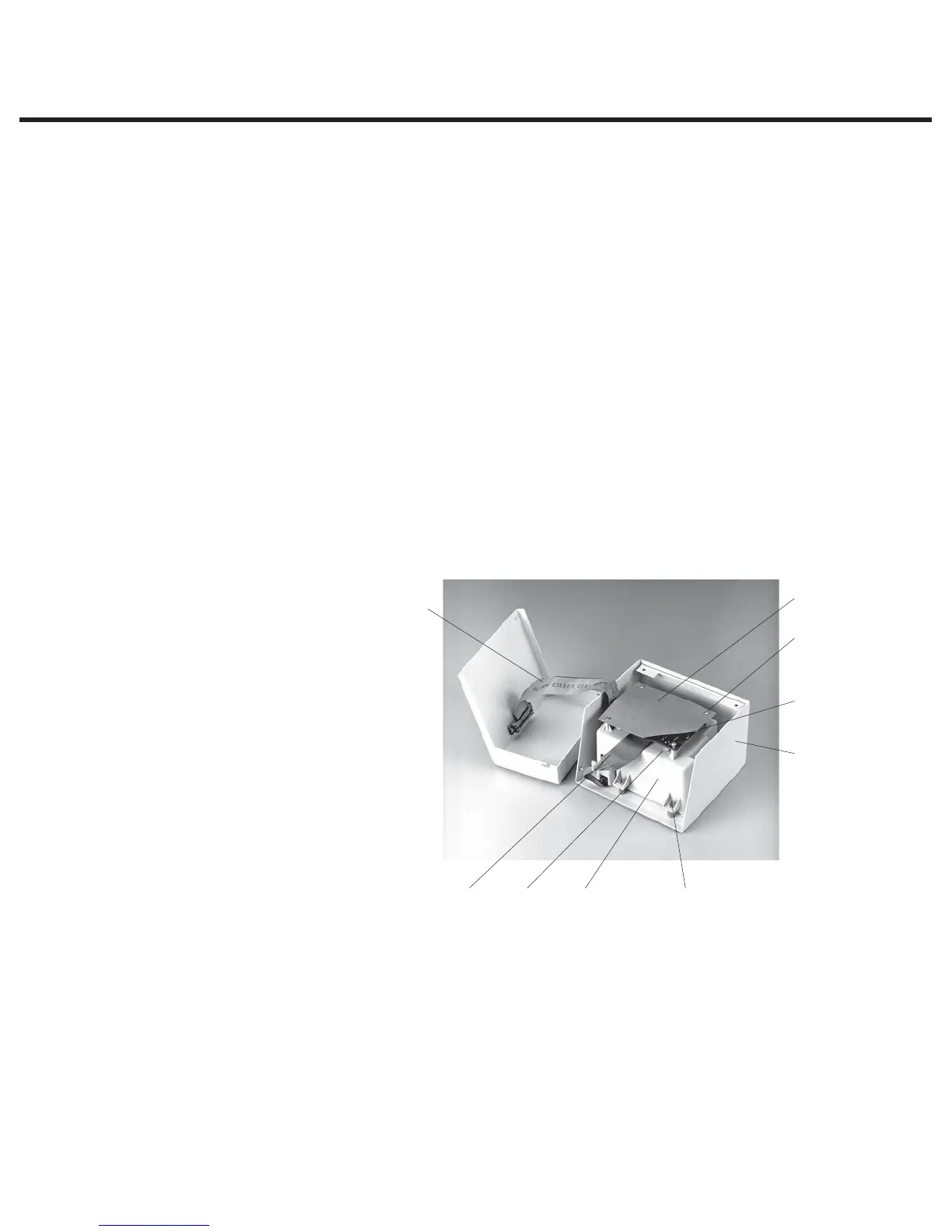
Removing and Replacing the Printer Module
To remove the printer module assembly (1), proceed as follows (see Figure 2):
1. Place the printer cover (2) containing the printer module (1) on a clean work surface to avoid
scratching the cover surface.
2. Remove four screws (3) securing the printer module assembly to the printer cover. Retain the
screws.
3. Remove the module from the printer cover.
To replace the printer module (1), follow these steps (see Figure 2):
1. Install the printer module assembly (1) in the printer cover (2) using the four screws (3) retained
during disassembly.
2. If the module contains a new printer interface board, or a new printer, the print quality may
require adjustment. See ‘Printer Interface Board’ and ‘Adjusting Print Quality’ below.
1
2
3
4
5
6
7
8
9
1. Printer module assembly
2. Printer cover
3. Screws (for module)
4. Printer interface board
5. Printer driver cable
6. Printer interface ribbon cable
7. Screws (for board)
8. Printer interface board shield
9. R21 contrast adjustment
Figure 2
Printer interface board shield — with cut-away to show board
STATIM 2000/2000S/2000 G4 Service Guide