Page 171
STAT
IM
2000/2000S Service Guide
96-108639 Rev 3.0
8. Water Pumps, Reservoir, and Compressor
STATIM 2000/2000S/2000 G4 Service Guide
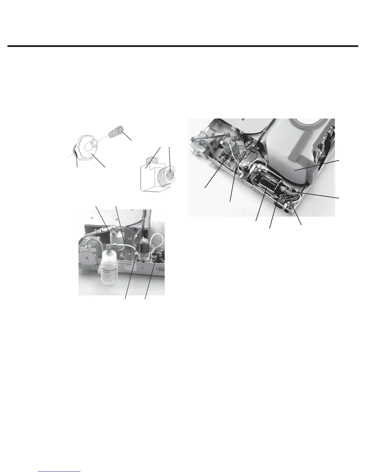
Performing internal pump filter maintenance
For filter maintenance on internal filters located in the pump, proceed as
follows (see Figure 6):
Tip: This can be undertaken with the pump in place, but it is easier if the pump is removed
from the unit.
If the choice is to have the pump still located in the unit:
1. Drain the reservoir or crimp the pump inlet hose to prevent water leaking from the
disconnected hose, cut the cable tie (2) holding the hose and remove it from the pump inlet
fitting (4).
2. Using a 3/8-inch wrench disconnect the white Teflon™ pump tube (5) from the pump outlet
fitting (6).
3. Using a 9/16-inch wrench on the pump inlet fitting (4) and a 9/16-inch wrench on the pump
body inlet fitting (7), unscrew the inlet fitting.
4. There is a mesh filter (8) inside the pump inlet fitting and a rubber seal (9) on the outside
threaded end of the fitting. From the threaded end of the fitting, insert a blunt instrument and
gently push the filter out. If the filter does not come out, soak the fitting until any deposits have
been dissolved.
1. Reservoir
2. Cable tie
3. Pump inlet tube
4. Pump inlet fitting
5. Teflon™ tube
6. Right-angle pump outlet fitting
7. Pump body fitting
8. Mesh filter, integral to item 4
9. Rubber seal, integral to item 4
10. Pump
11. Pump body outlet fitting (obscured)
12. Steam generator
13. Insert with mesh filter, integral to item 6
94
6813
611
12 5
Figure 6
5
6, 7
(obscured)
4
10
2
3
1