Page 163
STAT
IM
2000/2000S Service Guide
96-108639 Rev 3.0
7. Electrical and Electronic Components
STATIM 2000/2000S/2000 G4 Service Guide
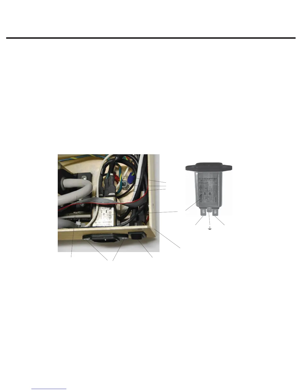
Receptacle / Line Filter
Some STAT
IM
units contain an A.C. inlet receptacle / line filter. It is difficult to determine
whether a line filter has failed or not. If the unit blows mains fuses in the service panel, there
may be a short in the line filter. Disconnect all leads from the mains input and output and test
for short circuits.
Removing the Receptacle / Line Filter
To remove a line filter (1), proceed as follows, (See Figure 23):
1. Turn the power switch (2) OFF, and unplug the power cord (3) from the wall outlet.
2. Remove the power cord from the unit. See, Removing a Detachable Power Cord.
3. Disconnect the white wire (4a) from receptacle line filter position N, the black wire (4b) from
line filter position P and the green wire (4c) from line filter position. If access to the back of the
line filter is impeded, disconnect the pump inlet tube (5).
4. Remove the screws (6) holding the filter to the chassis (7) and remove the filter.
Replacing/refitting the Receptacle / Line Filter
To replace/refit a line filter (1), proceed as follows, (See Figure 23):
1. Insert the line filter in the opening in the chassis (7). The P and N fast-on spade terminals
should face up, and the ground terminal should face down.
2. Insert and tighten the screws (6) holding the line filter, using Loctite in the threaded holes in the
chassis.
3. Connect the white wire (4a) from the power switch to line filter position N and the black wire
(4b) from the power switch to line filter position P.
4. Connect the green wire (4c) from the ground post to line filter position.
5. If the pump inlet tube (5) was moved, reinstall the tube.
Position N
Position P
1. Line filter
2. Power switch
3. Line cord (not shown)
4.
a. White wire
b. Black wire
c. Green wire
5. Pump inlet tube
6. Screw
7. Chassis
Figure 23
1
2
7
6
4a, b, c
5