Page 162
STAT
IM
2000/2000S Service Guide
96-108639 Rev 3.0
7. Electrical and Electronic Components
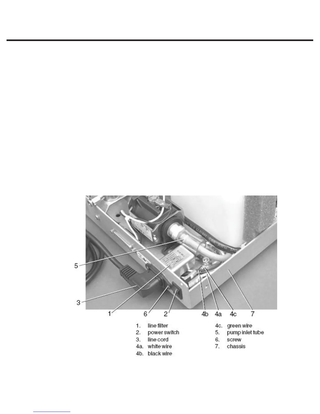
Replacing/refitting the A.C. Power Switch
To replace/refit the power switch (1), proceed as follows, (See Figure 22):
1. Orient spade terminals 1a and 2a downwards and press the power switch into the clearance
hole in the chassis. Apply pressure evenly top and bottom until the bezel rests against the
chassis (7) wall.
2. Connect the white wire (fig. 21, item 7a) extending from controller board terminal J1-1 to the
lower right-hand power switch spade terminal labelled 1a and the black wire (fig. 18, item
7b) extending from controller board terminal J1-2 to the lower left-hand power switch spade
terminal, labelled 2a.
3. Connect the white wire (4a) from either the attached power cord, the A.C. inlet receptacle or
the A.C. inlet receptacle / line filter to the upper right-hand power spade terminal labelled 1,
and the black wire (4b) to the upper left-hand spade terminal labelled 2, nearest the pump.
4. A dielectric strength test (Hi-Pot) and a protective bonding impedance test (ground continuity)
should be performed on the STATIM unit at this stage.
NOTE: These tests must be performed on the STATIM again once the work is completed and
the cover has been returned to the unit.
5. Plug the power cord (3) into the wall receptacle and turn the power switch (2) ON. Observe the
LCD and indicator lights to determine that power is present.
Figure 22
STATIM 2000/2000S/2000 G4 Service Guide