Page 154
STAT
IM
2000/2000S Service Guide
96-108639 Rev 3.0
7. Electrical and Electronic Components
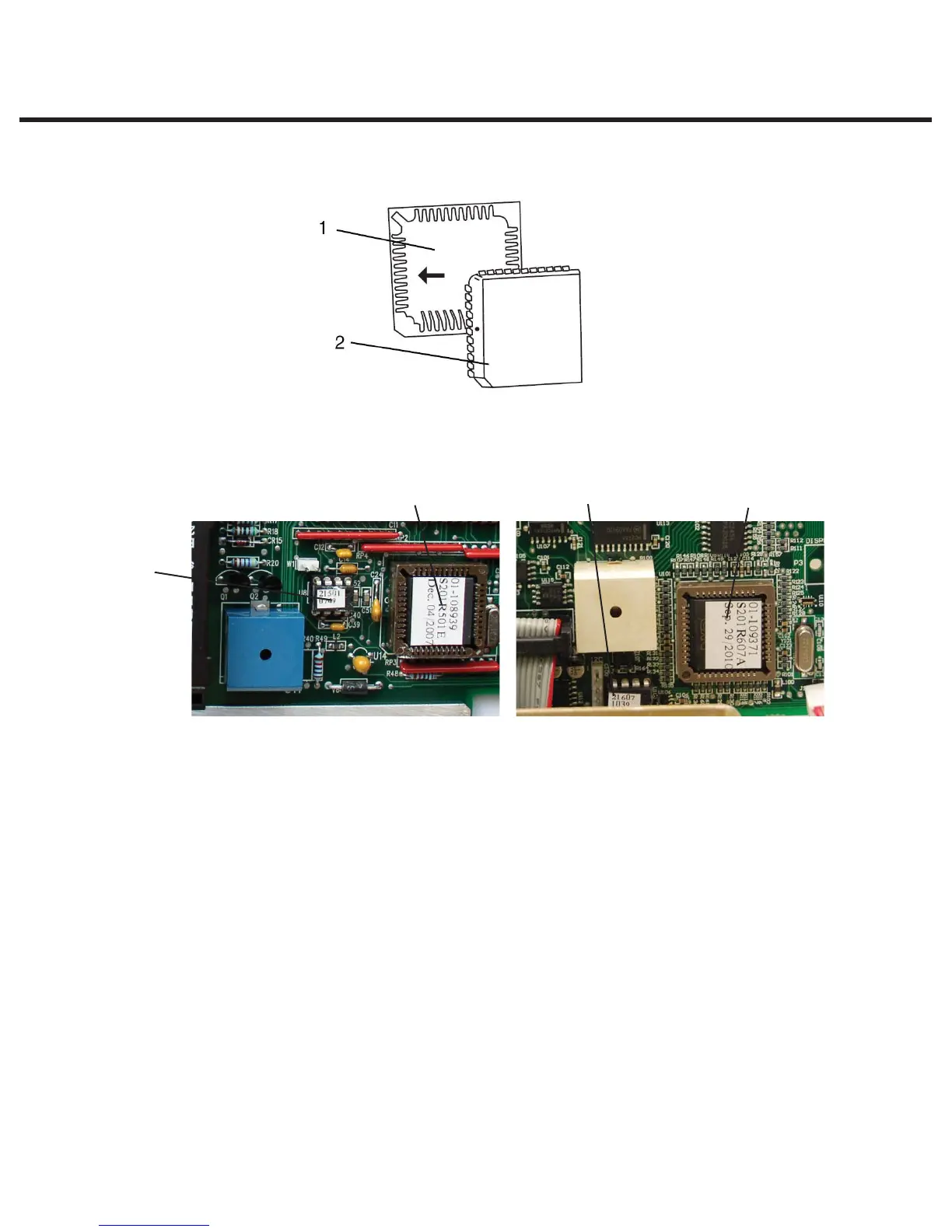
Revision 6.x and 7.x controller boards all have the following main processor configuration.
Both Revision 6.x and 7.x of controller boards also have a supplementary EEPROM located
near to the main processor.
Removing the Microprocessor (and Pre-Programmed EEPROM
where fitted).
Before removing or replacing the devices observe appropriate electrostatic discharge
precautions for the work area and technician. Ensure that the unit is powered OFF.
To remove the Microprocessor and pre-programmed EEPROM device if present, proceed as
follows:
1.
b. For revision 2.x/5.x, 3.x/4.x controller boards — Remove the microprocessor from
Controller Board socket using a 40-pin IC puller. Remove the EEPROM device from
Controller Board socket using an 8-pin IC puller.
DISCARD the microprocessor and EEPROM devices.
Note: The orientation of Pin 1 of the socket and Pin 1 of the EEPROM
Figure 17
Figure 18
Rev. 6.x Rev. 7.x
1. Microprocessor
2. 44-pin PLCC socket
EEPROM
Microprocessor EEPROM Microprocessor
STATIM 2000/2000S/2000 G4 Service Guide