Page 147
STAT
IM
2000/2000S Service Guide
96-108639 Rev 3.0
7. Electrical and Electronic Components
6.
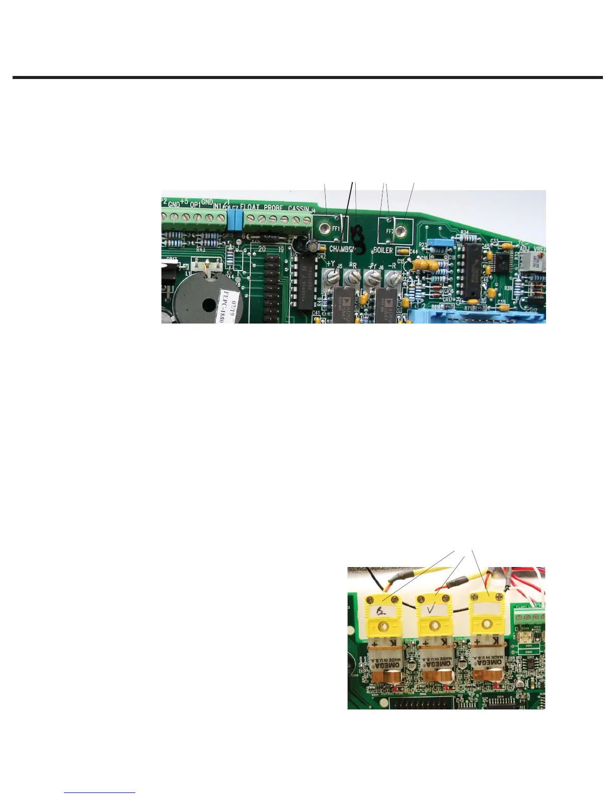
a. For all boards up to and including Rev. 6.x —
t Check the pre-bend on both thermocouple leads to ensure that they are the required
shape to go under the washers on the connections without touching anything other
than the terminal.
t
Note: One lead is colour coded: the unmarked lead is positive, +Y. the red lead
is negative, -R. Connect the unmarked lead to the terminal marked +Y on the
Controller Board. Connect the red lead to the terminal marked –R on the controller
board. Make sure there is extra lead length so that the wires do not break as the
screw is tightened.Ensure the wires are seated securely behind the respective
washers.
t Reconnect the steam generator thermocouple wires to the controller board terminal
positions BOILER +Y and -R (2).
t Reconnect the chamber thermocouple wires to the controller board terminal positions
CHAMBER +Y and -R (4).
t Reconnect the ground terminal from the position marked BOILER (3). Reconnect the
ground terminal from the position marked CHAMBER (5).
The two leads must not touch one another or any other component. Do not calibrate a
thermocouple until it is properly installed and positioned in the unit.
b. For all boards Rev. 7.x onwards —
t Plug in the thermocouple connectors.
There are three for non S (‘boiler’,
‘chamber’ and ‘validation’) and two
for S class (‘boiler’ and ‘chamber’) (6).
t Plug in the float connector on units
where the water quality + float
reservoirs are fitted (7).
Figure 9
Figure 10
3
6
245
STATIM 2000/2000S/2000 G4 Service Guide