Page 213
STAT
IM
2000/2000S Service Guide
96-108639 Rev 3.0
10. Armature, Isoplate, and Probe Bracket and Chamber Thermocouple
STATIM 2000/2000S/2000 G4 Service Guide
For revision 7.x controller boards
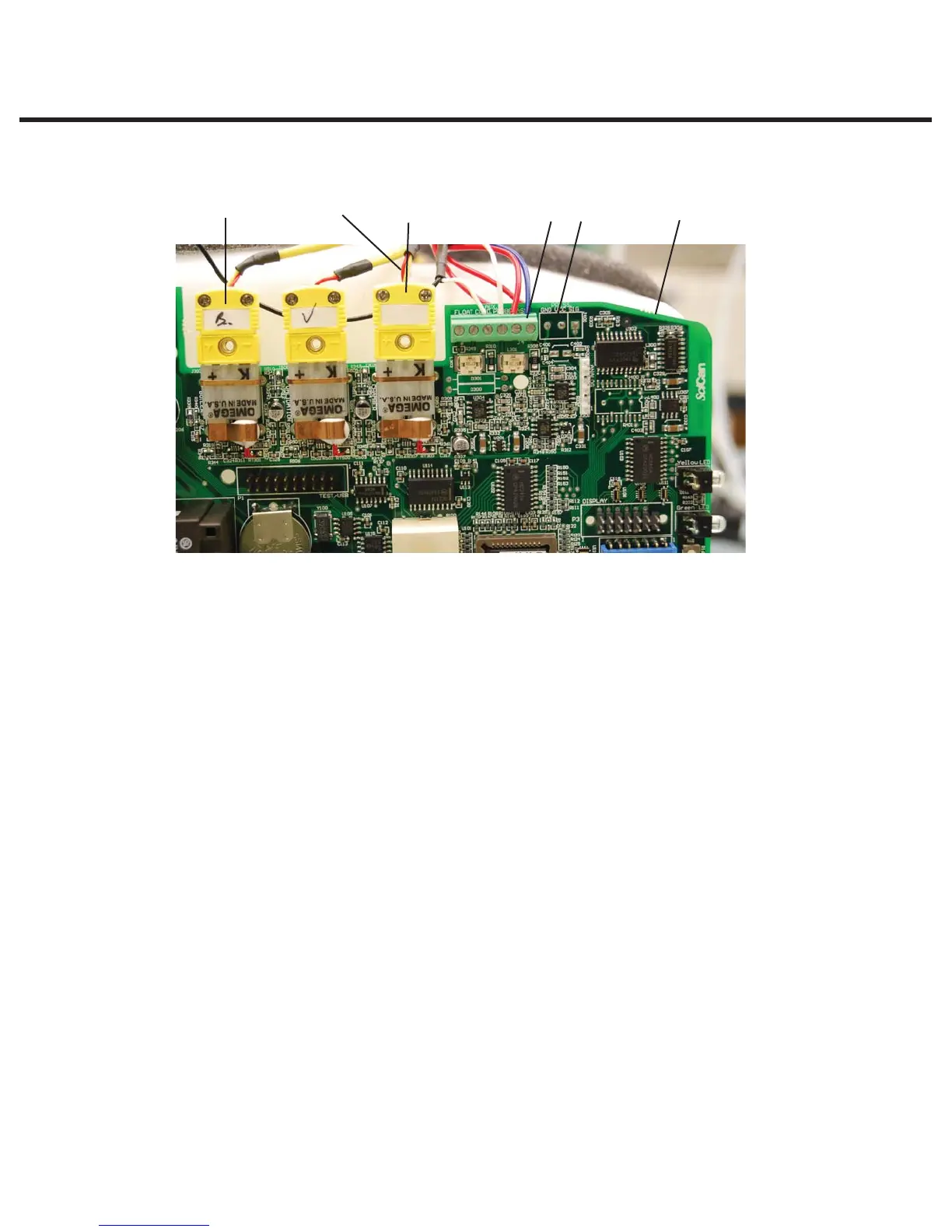
c. Disconnect the chamber thermocouple plug (7) from the socket on the controller board.
2. Remove the microswitch (4) leads from controller board block connector positions labelled
CASSIN.
3. Carefully cut the cable ties (5) securing the microswitch leads and other wires to the top of the
armature (26).
4. Carefully cut the cable tie (9) holding the compressor tube (10) onto the check valve inlet (11)
and pull the tube off the valve.
5. Disconnect the compression nut (12) holding the steam generator outlet tube (13) to the steam
generator outlet fitting (14).
6. Remove the two screws (15) holding the steam generator bracket (16) to the chassis.
7. Disconnect the compression nut (17) holding the exhaust tube (18) to the solenoid valve inlet
fitting (19).
8. Remove the two screws (20) that hold the solenoid valve assembly (21) to the chassis.
9. The probe bracket assembly (22) is held by four hex socket cap screws with flat washers (23).
The bottom of the probe bracket assembly has two mounting slots. The top of the bracket has
two mounting holes. Remove the top two screws with an Allen key. Loosen the bottom cap
screws to allow the bracket to slide up and out of the chassis. Note the foam probe bracket
gasket (24 - not shown) mounted on the plastic end part of the armature (26).
10. Disconnect the compression nut (25) holding the steam generator outlet tube (13) to the probe
inlet fitting (27). Remove the steam generator outlet tube (13) and the solenoid valve exhaust
tube (18) from the probe bracket assembly. (Discard them if fitting a new bracket).
671432
Figure 4
1. Chamber
thermocouple
leads
2. Controller board
3. Flag terminal
4. Microswitch leads
5. Cable tie
6. Steam generator
Thermocouple plug
7. Chamber
thermocouple plug