Reference contour field
T
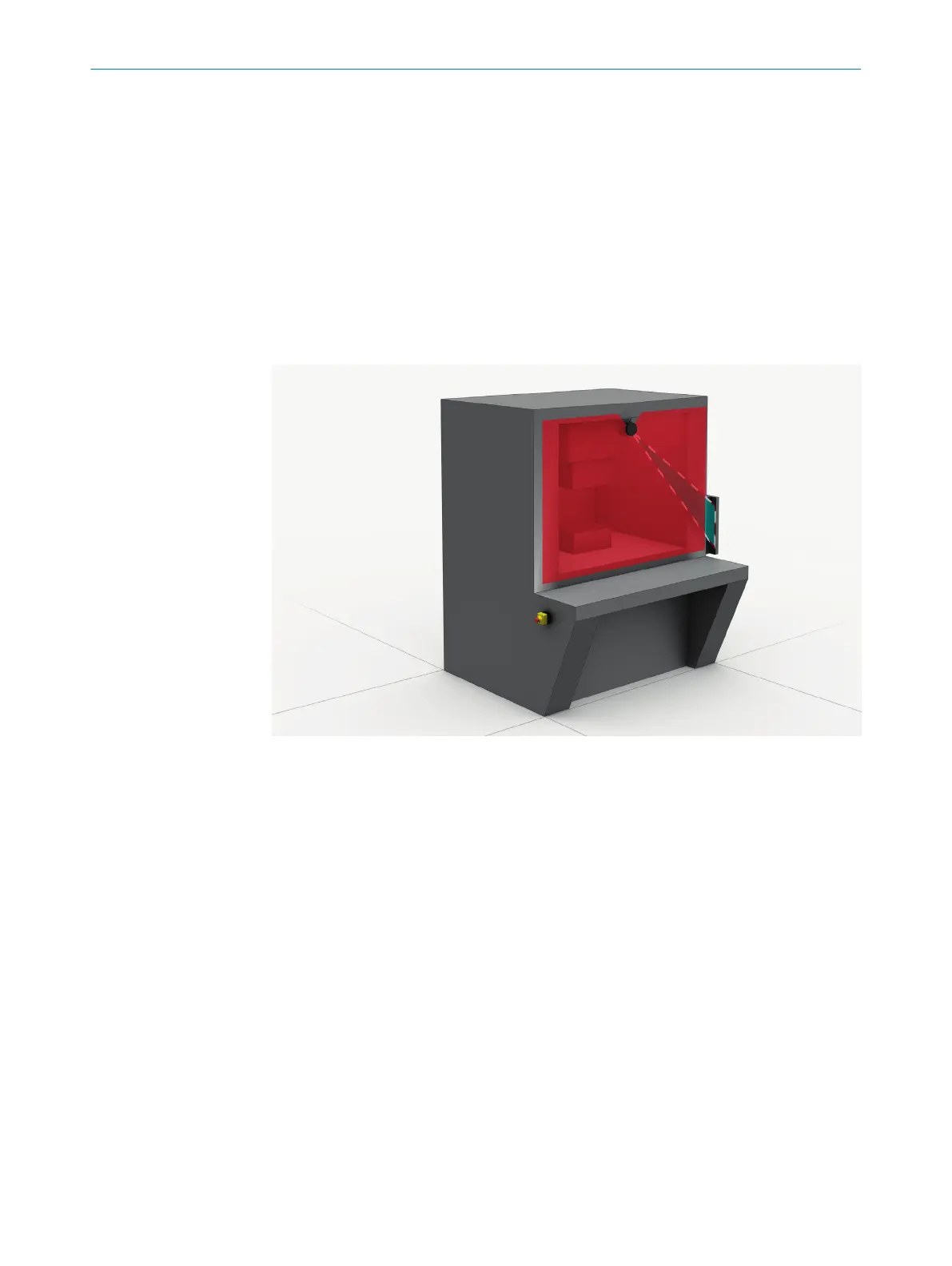
he contour as reference field monitors a contour of the environment. The safety laser
scanner switches all safety outputs to the OFF state if a contour does not match the set
parameters, because, for example, the mounting of the safety laser scanner has been
changed.
National and international standards require or recommend that a reference contour is
monitored, if the safety laser scanner is used in vertical operation for hazardous point
protection or for access protection.
The reference contour field detects unintentional and intentional changes to the posi‐
tion or alignment of the safety laser scanner. Unintentional changes may be caused by
vibrations for example. An example of an intentional change is deliberate tampering to
disable the functionality of the safety laser scanner.
Figure 6: Reference contour field, shown in blue-green in this document
Contour detection field
T
he contour detection field monitors a contour of the environment. The electro-sensitive
protective device switches the associated safety outputs to the OFF state if a contour
does not correspond to the set specifications, e.g. because a door or flap is open.
The contour detection field is used for detecting changes in the environment and only
switches the outputs in the current monitoring case. By contrast, the reference contour
field is used for detecting changes at the safety laser scanner and switches all safety
outputs.
Collision protection field
T
he collision protection field detects oncoming industrial trucks in narrow aisles based
on the reference target. It has a greater scanning range than a protective field. With
the collision protection field, collisions of industrial trucks in narrow aisles can be safely
prevented.
The collision protection field is not suitable for detecting people.
The collision protection field may only be used in narrow aisles.
3 P
RODUCT DESCRIPTION
18
O P E R A T I N G I N S T R U C T I O N S | microScan3 Pro I/O 8025424/1ELL/2022-01-21 | SICK
Subject to change without notice