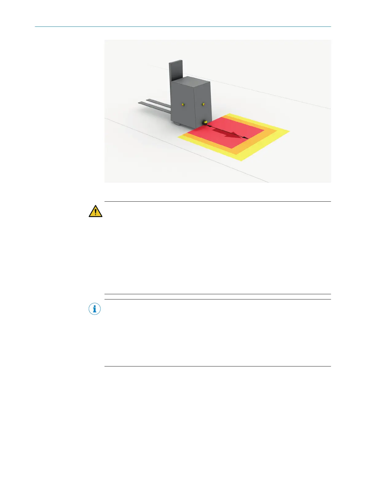
Figure 33: Mobile application in horizontal operation for hazardous area protection
DANGER
H
azard due to lack of effectiveness of the protective device
In the case of non-compliance, it is possible that the dangerous state of the machine
may not be stopped or not stopped in a timely manner.
1. Calculate the minimum dimensions required for the protective field taking into
account the supplements described in the following text along with the specific
requirements imposed by your application.
2. Take this calculation and the specifications in these instructions into account
when mounting the safety laser scanner.
3. Take this calculation and the specifications in these instructions into account
when configuring the safety laser scanner.
NOTE
•
In a mobile applic
ation, a resolution of 70 mm (leg detection) is sufficient for
detecting people. By contrast with stationary hazardous point protection, this is
also true for a low mounting height, as the safety laser scanner moves together
with the vehicle.
•
In the following calculation examples, only the vehicle speed is taken into account,
not the speed of a walking person. This is based on the assumption that the
person recognizes the danger and stands still.
4.3.9.1 Protective field length
The protective field must be designed so that it detects a person at a minimum
distance from the hazardous point. This distance is required to ensure that the vehicle
comes to a stop before it reaches a person or an object.
In mobile hazardous area protection, the minimum distance typically defines the pro‐
tective field length required. When calculating the protective field length, the impact of
turning must be considered separately.
If you define a number of monitoring cases with different protective fields, you must
calculate the protective field size separately for each protective field used.
4 P
ROJECT PLANNING
48
O P E R A T I N G I N S T R U C T I O N S | microScan3 Pro I/O 8025424/1ELL/2022-01-21 | SICK
Subject to change without notice