1500 2000 2500 3000 3500 l [mm]
7
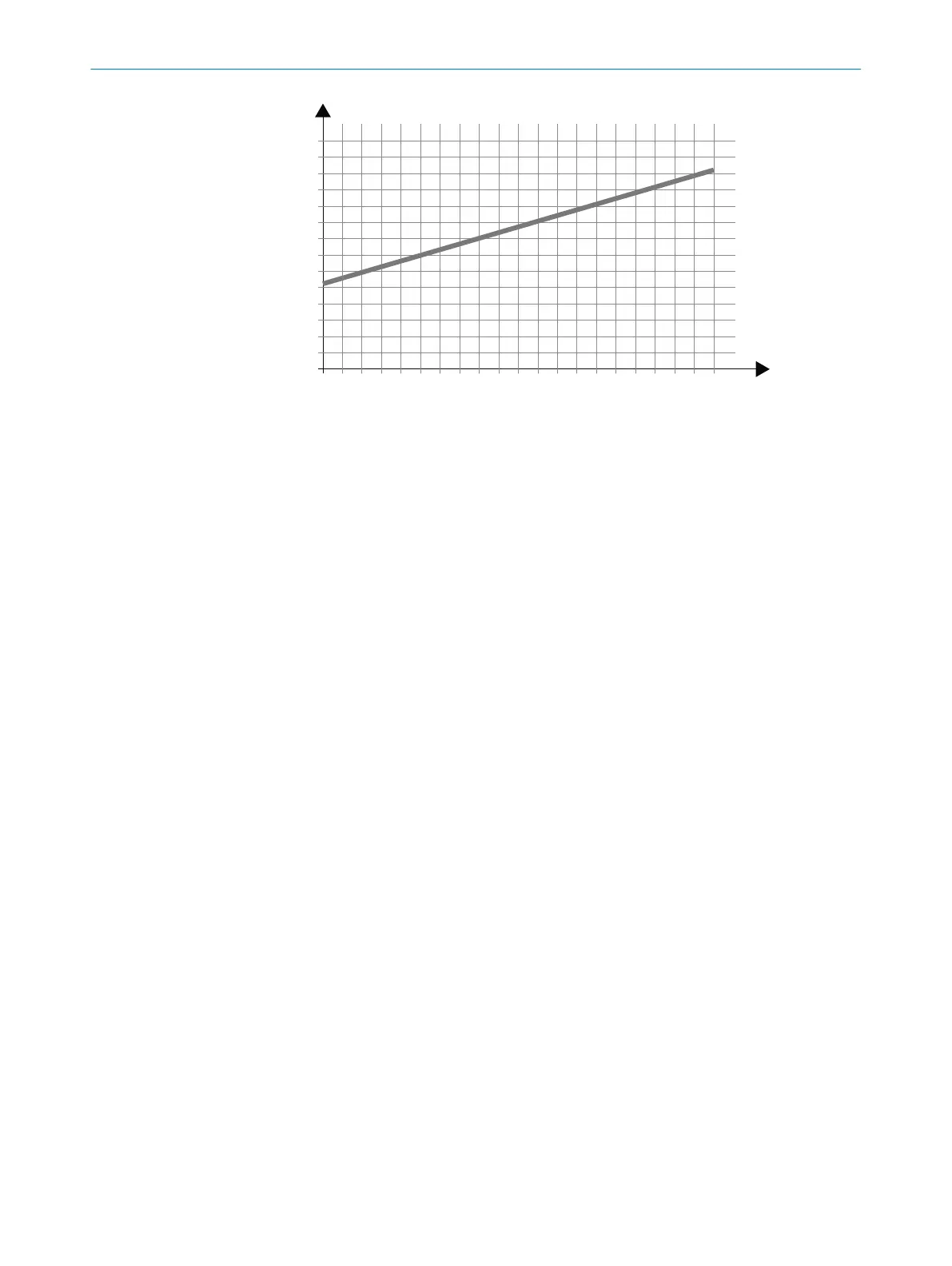
p [mm]
6
5
4
3
2
1
0
Figure 39: Permissible guide tolerance of the industrial truck
p Maximum permissible play per guide element
l Distance between front and rear guide element
If the distance between the front and rear guide element is 1.8 m, the maximum
per
missible tolerance is ±3 mm per guide element.
Determination of the guide play on the vehicle:
•
For mechanical guides: If the left-hand guide elements are in contact with the
guide rail (0 mm distance), then the distance between the right-hand elements
and the rail must not exceed 2 × 3 mm = 6 mm.
•
For inductive guides: The deviation of the industrial truck from the guiding line
must not exceed ±3 mm.
4.3.10.1 Protective field in narrow aisle
Overview
If t
he safety laser scanner in the narrow aisle is not used exclusively for collision
protection, but also for person detection, then you must configure a protective field in
addition to the collision protection field.
The Suggest field function is not suitable because the position of the industrial truck in
the aisle varies and the industrial truck makes yawing movements.
During commissioning, a test object in accordance with DIN 15185-2 must be used in
driving tests to ensure that the protective field is adequately dimensioned.
Protective field width
T
he protective field must be wide enough to reliably detect a person in the edge area in
front of the rack.
If the protective field extends to the front of the rack, availability may be affected.
Therefore, a distance between the protective field and the front of the rack is required.
A distance of the TZ value is recommended to ensure availability (TZ = tolerance
zone of the safety laser scanner, see "Data sheet", page 178). The guide play of the
industrial truck also has an influence on availability, see "Example for determining the
permissible guide play of the industrial truck", page 54.
The distance between the center axis of the test object according to DIN 15185-2 and
the front of the rack is normally 125 mm.
5)
If the distance is greater than 125 mm,
a supplement to the protective field length must be taken into account. The distance
must not exceed 200 mm.
PROJECT PLANNING 4
8025424/1ELL/2022-01-21 | SICK O P E R A T I N G I N S T R U C T I O N S | microScan3 Pro I/O
55
Subject to change without notice