•
In t
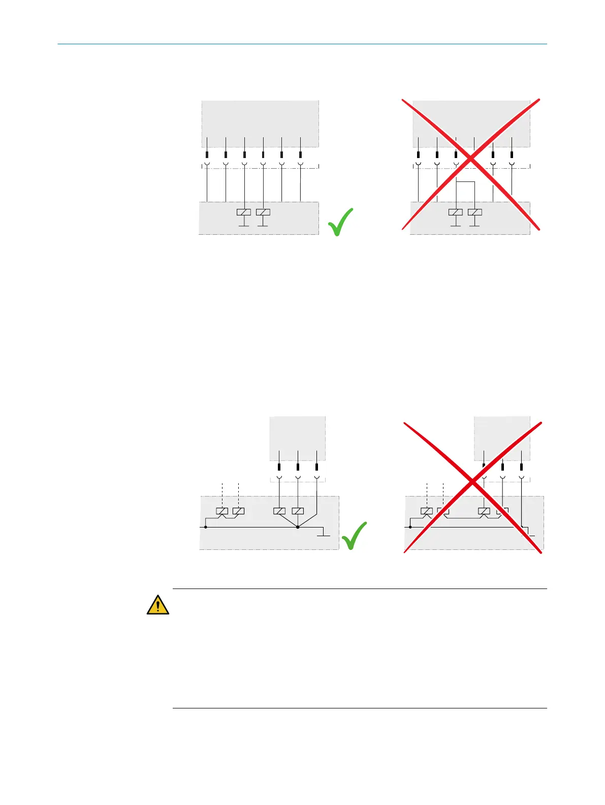
he machine controller, both signals from an OSSD pair must be processed
separately.
Figure 41: Dual-channel and separate connection of the OSSDs of an OSSD pair
•
The machine must switch to the safe state if, at any time, at least one OSSD in an
OSSD pair switches to the OFF state.
•
Only one OSSD pair can be used in each safety function.
•
Prevent the formation of a potential difference between the load and the protec‐
tive device. If you connect loads to the OSSDs (safety outputs) that then also
switch if controlled with negative voltage (e.g., electro-mechanical contactor with‐
out reverse polarity protection diode), you must connect the 0 V connections of
these loads and those of the corresponding protective device individually and
directly to the same 0 V terminal strip. In the event of a fault, this is the only way to
ensure that there can be no potential difference between the 0 V connections of
the loads and those of the corresponding protective device.
Figure 42: No potential difference between load and protective device
DANGER
H
azard due to lack of effectiveness of the protective device
In the case of non-compliance, it is possible that the dangerous state of the machine
may not be stopped or not stopped in a timely manner.
Downstream contactors must be positively guided and monitored depending on appli‐
cable national regulations or required reliability of the safety function.
b
Make sure that downstream contactors are monitored (external device monitoring,
EDM).
•
Eac
h OSSD pair in the safety laser scanner is equipped with an internal EDM.
PROJECT PLANNING 4
8025424/1ELL/2022-01-21 | SICK O P E R A T I N G I N S T R U C T I O N S | microScan3 Pro I/O
65
Subject to change without notice