Mounting in the machine or vehicle’s paneling
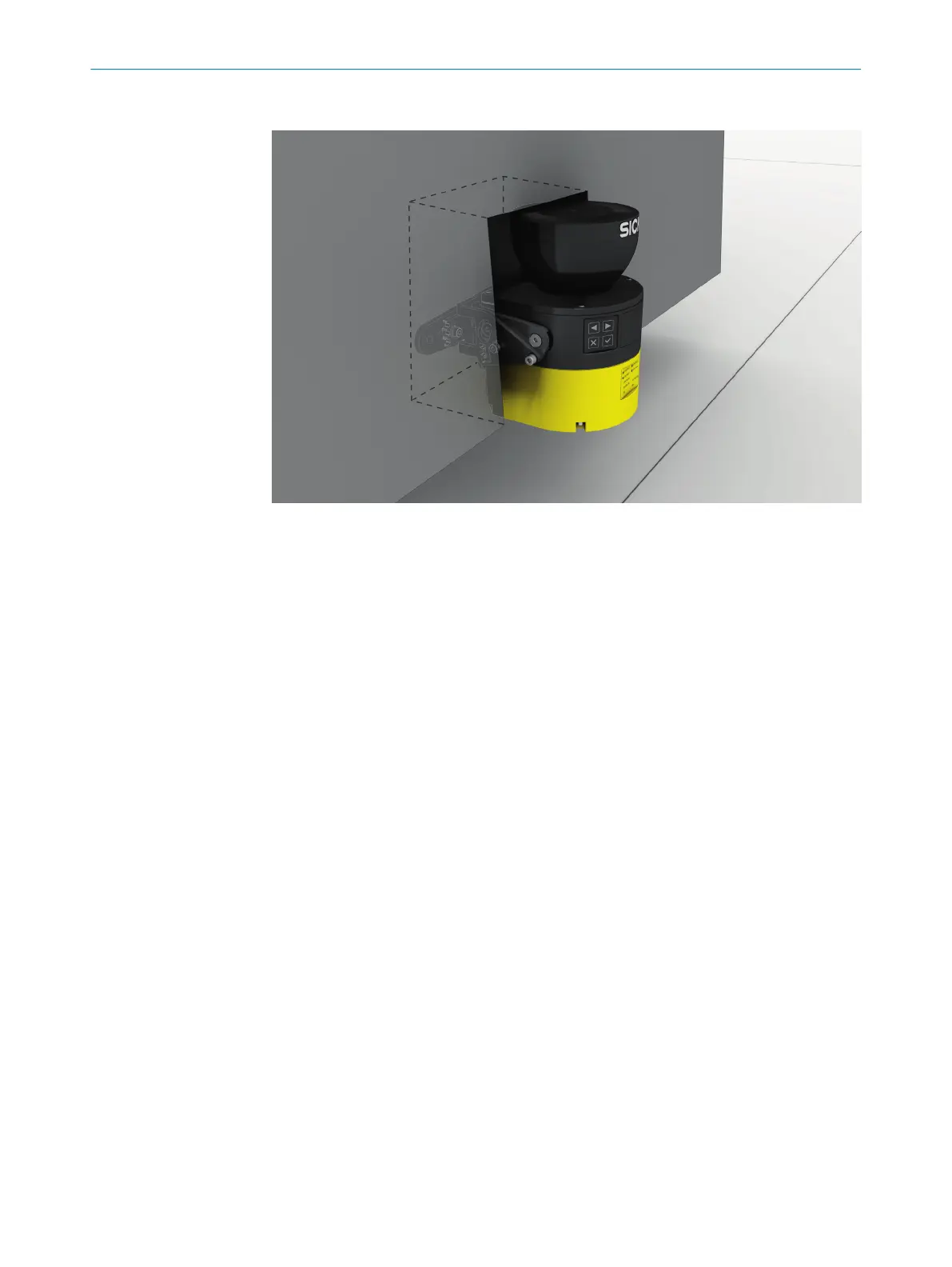
Figure 22: Mounting in vehicle paneling (example)
b
If a v
iewing slit is required, make sure that its size is sufficient, see "Dimensional
drawings", page 205.
4.3.3 Response time of the safety laser scanner
The safety laser scanner’s response time must be taken into account, among other
t
hings, so that the safety laser scanner can be positioned in a suitable location and the
protective fields can be sized correctly.
The response times are specified in the technical data, see "Response times",
page 186.
The response time of the safety laser scanner resulting from current settings is shown
in Safety Designer.
4.3.4 Reference contour monitoring
Vertical operation
N
ational and international standards require or recommend that a reference contour is
monitored if the angle between access direction and scan plane exceeds 30°. With the
reference contour field, the safety laser scanner monitors the distance to a contour of
the environment (e.g. a wall) in order to detect inadvertent adjustment or manipulation.
Configuring the reference contour field during vertical operation
•
In man
y cases, it makes sense to use the floor and lateral vertical passage
boundaries (e.g. door frames) as a reference contour.
•
The resolution of the reference contour field specifies how large a gap in the
contour or an object in the reference contour field must be for the reference
contour field to detect the gap or object in any case. Smaller gaps or objects can
also trigger detection in some cases.
•
The length of the monitored contour must be greater than the set resolution of the
reference contour field.
•
The reference contour field has an adjustable tolerance band. If the safety laser
scanner does not detect the reference contour within the tolerance band, all
4 P
ROJECT PLANNING
30
O P E R A T I N G I N S T R U C T I O N S | microScan3 Pro I/O 8025424/1ELL/2022-01-21 | SICK
Subject to change without notice