7. Install the cover plate on the safety laser scanner. Tightening torque: 2.25 Nm …
2.75 Nm.
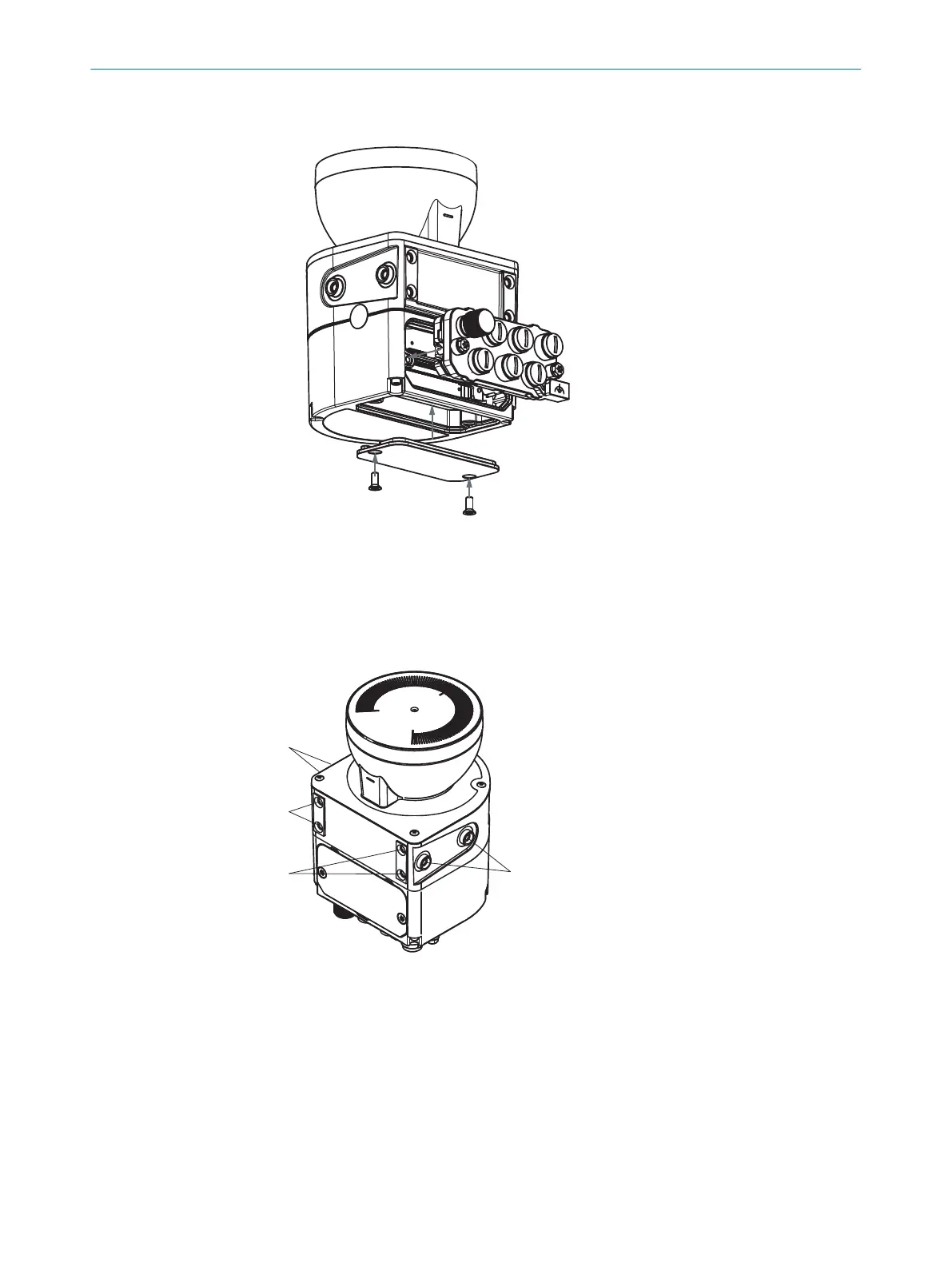
Figure 52: Installing the rear system plug
5.3.2 Direct mounting
The safety laser scanner has 4 M5 threaded holes on the back. If you are able to drill
t
hrough the mounting surface from the rear, you can mount the safety laser scanner
directly using these threaded holes.
Figure 53: Mounting the safety laser scanner directly
1
Rear M5 threaded hole
2
Side M5 threaded hole
b
Use eit
her the rear or the side M5 threaded holes for direct mounting, see
figure 53, page 89.
b
Use all four rear or all 4 side M5 threaded holes for direct mounting, so that the
values given in the data sheet for vibration and shock resistance are achieved.
b
Maximum depth of thread engagement: 7.5 mm (see "Dimensional drawings",
page 205).
b
Tightening torque: 4.5 Nm to 5.0 Nm.
MOUNTING 5
8025424/1ELL/2022-01-21 | SICK O P E R A T I N G I N S T R U C T I O N S | microScan3 Pro I/O
89
Subject to change without notice