NOTE
In some c
ases, it is not possible to define when to switch (for example because
processing times of the machine vary) or the time advance means that the monitoring
of an area finishes too early. Follow one of the following recommendations in these
cases:
b
Allow the two protective fields to partially overlap.
b
Temporarily monitor both hazardous areas simultaneously.
Complementary information
If y
ou use a host-guest group and the local inputs of the host control the monitoring
case switching of a guest device, then you must consider the transmission time in the
host-guest group and the processing time in both devices.
You can use the following formula to calculate how much time monitoring case switch‐
ing takes:
t
CSR
= t
IH
+ t
OH
+ t
T
+ t
IG
+ t
ID
Where:
•
t
CSR
= time required for switching between monitoring cases in milliseconds (ms)
•
t
IH
= 12 ms (processing time for local control inputs of the host)
•
t
OH
= 35 ms (time for processing and output of the host)
•
t
T
= transmission time in the host-guest group (see Safety Designer, window
Connection overview, column Response time via network [ms]:)
•
t
IG
= 28 ms (time for guest input)
•
t
ID
= input delay for the control inputs in milliseconds (ms)
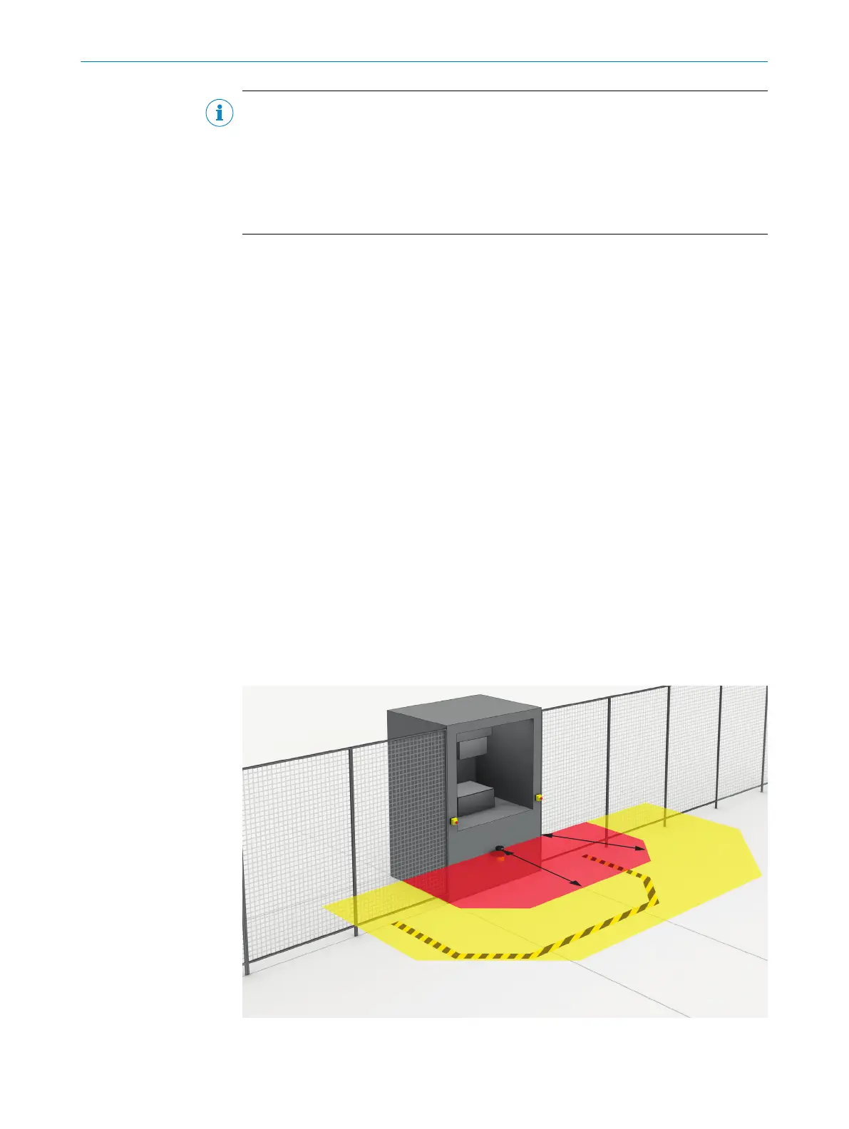
4.3.6 Hazardous area protection
The safety laser scanner is mounted with a horizontal scan plane in a stationary
applic
ation, for example on a machine where the hazardous area is not completely
surrounded by a physical guard. During hazardous area protection, the safety laser
scanner detects a person’s legs. The protective field is parallel to the person’s direction
of approach.
Figure 25: Stationary application with horizontal scan plane for hazardous area protection
4 P
ROJECT PLANNING
34
O P E R A T I N G I N S T R U C T I O N S | microScan3 Pro I/O 8025424/1ELL/2022-01-21 | SICK
Subject to change without notice