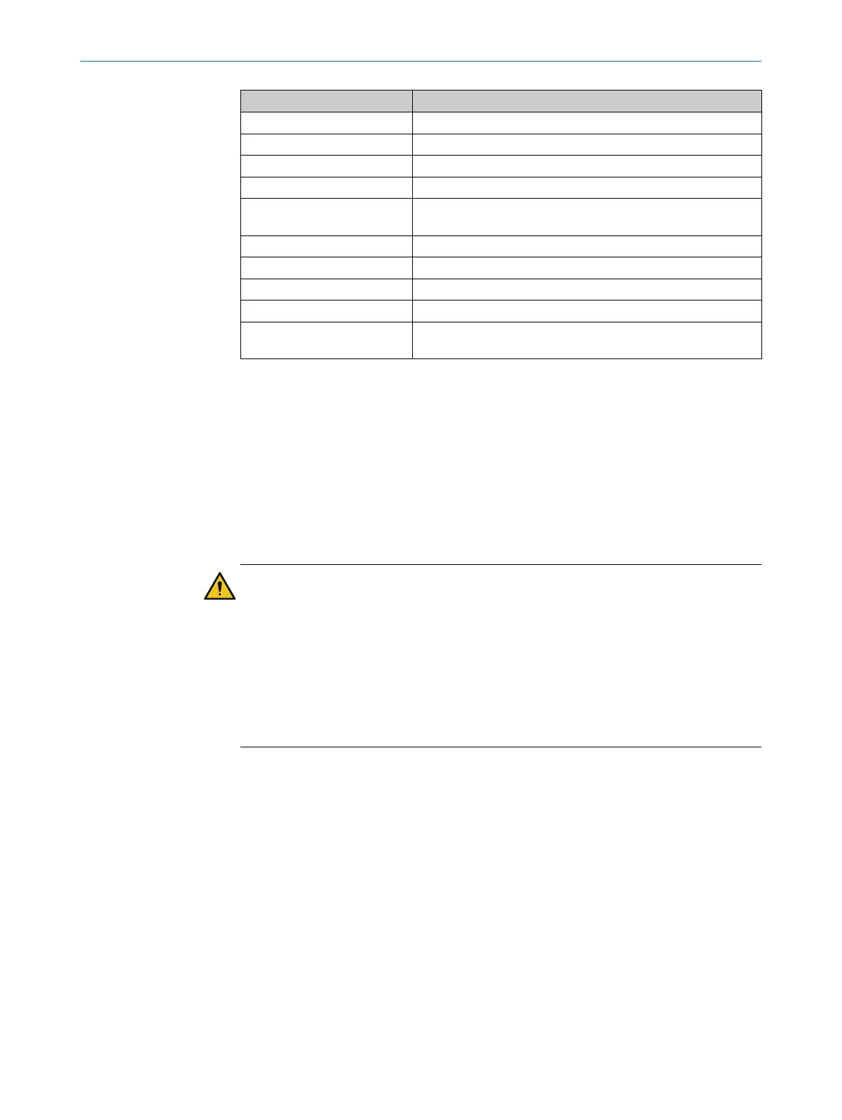
microScan3 Pro I/O
At front screen 18 mm × 4 mm
At 4.0 m distance 8 mm × 14 mm
At 5.5 m distance 4 mm × 19 mm
At 9.0 m distance 2 mm × 30 mm
Divergence of collimated
be
am
0.17°
Receiving angle 0.75°
Pulse duration Typ. 4 ns
Average output power 9.2 mW
Laser class 1M
Measurement error with
me
asurement data output
Typ. ± 25 mm
1)
In the event of heavy contamination, the safety laser scanner displays a contamination error and
s
witches all safety outputs to the OFF state.
2)
In close proximity (50 mm-wide area in front of the optics cover), the detection capability of the safety
laser scanner may be restricted. If required, this area must be secured using an undercut or frame, for
example.
3)
W × H when the laser beam exits at a 90° angle to the front.
13.4 Response times
The protective device’s response time is the maximum time between the occurrence of
t
he event leading to the sensor’s response and supply of the switch-off signal to the
protective device’s interface (for example OFF state of the OSSD pair).
DANGER
H
azard due to lack of effectiveness of the protective device
In the case of non-compliance, it is possible that the dangerous state of the machine
may not be stopped or not stopped in a timely manner.
In addition to the protective device’s response time, further signal transmission and
processing also influence the time up until the end of the dangerous state. These
include the network cycle time, a control’s processing time and the response times of
downstream contactors, for example.
b
Take the time for further signal transmission and processing into account.
Response time
T
he safety laser scanner’s response time depends on the following parameters:
•
Scan cycle time
•
Set interference protection
•
Set multiple sampling
You can calculate the response time using the following formula:
t
R
= (t
S
+ t
I
) × n + t
O
The following rules apply:
•
t
R
= response time
•
t
S
= scan cycle time
°
Setting “30 ms”: t
S
= 30 ms
°
Setting “40 ms”: t
S
= 40 ms
°
Setting “50 ms”: t
S
= 50 ms
•
t
I
= time for interference protection
13 T
ECHNICAL DATA
186
O P E R A T I N G I N S T R U C T I O N S | microScan3 Pro I/O 8025424/1ELL/2022-01-21 | SICK
Subject to change without notice