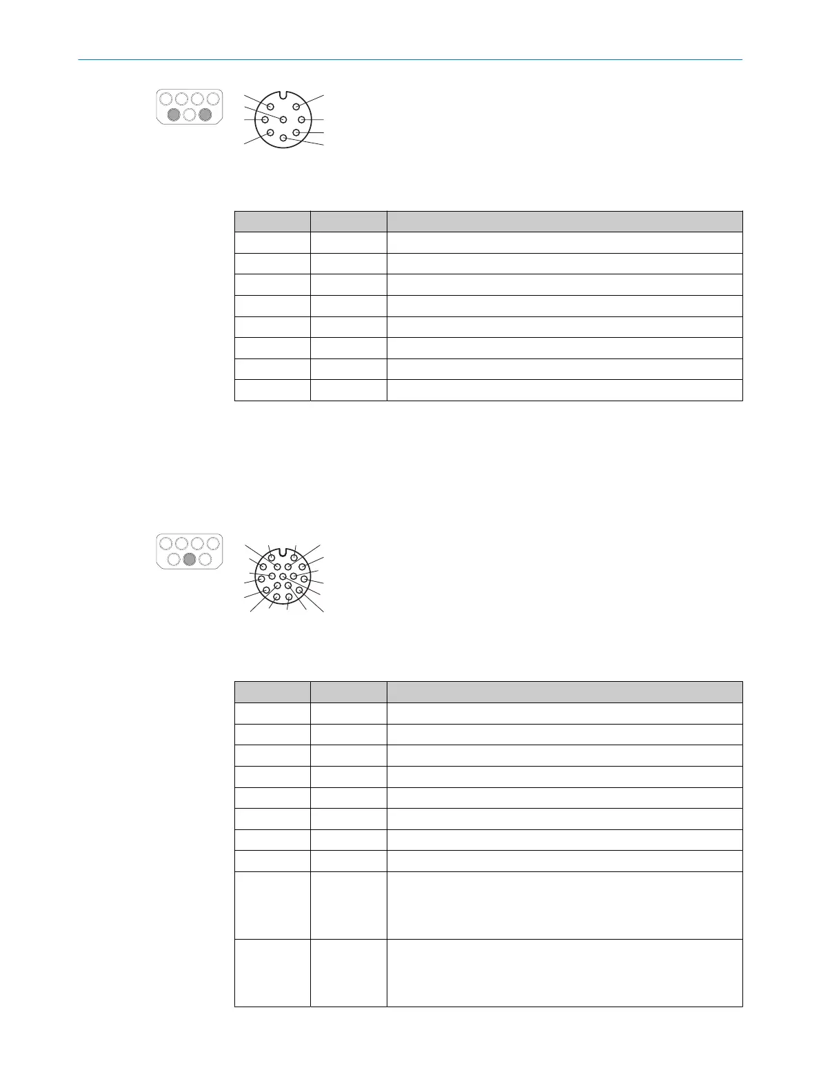
Figure 60: Pin assignment of dynamic control input (female connector, M12, 8-pin, A-coded)
Table 10: Pin assignment for dynamic control input
PIN Designation Function
1 nc Not connected
2 Inc 0° Incremental encoder signal (0°)
3 nc Not connected
4 Inc 90° Incremental encoder signal (90°)
5 nc Not connected
6 nc Not connected
7 0 V Inc Supply voltage for incremental encoder (0 V DC)
8 24 V DC Inc Supply voltage for incremental encoder (+24 V DC)
6.3.6 Local inputs and outputs 2 (XG4)
The local inputs and outputs are connected on the device side via 17-pin, A-coded M12
f
emale connectors.
If both 17-pin connections are used, both 17-pin cables must be clearly marked to
prevent confusion when replacing the device.
1 2
6
7 14
12
3
4
5
8
9
10
11
13
15
17
16
Figure 61: Pin assignment of inputs and outputs 2 (female connector, M12, 17-pin, A-coded)
Table 11: Pin assignment for local inputs and outputs 2
PIN Designation Function
1 OSSD 3.A OSSD pair 3, OSSD A
2 OSSD 3.B OSSD pair 3, OSSD B
3 OSSD 4.A OSSD pair 4, OSSD A
4 OSSD 4.B OSSD pair 4, OSSD B
5 nc Not connected
6 nc Not connected
7 nc Not connected
8 nc Not connected
9 Uni-I 11 Universal input 11, configurable:
•
S
tatic control input F1
•
Universal input: sleep mode, restarting the device, pausing
event recording
10 Uni-I 12 Universal input 12, configurable:
•
S
tatic control input F2
•
Universal input: sleep mode, restarting the device, pausing
event recording
ELECTRICAL INSTALLATION 6
8025424/1ELL/2022-01-21 | SICK O P E R A T I N G I N S T R U C T I O N S | microScan3 Pro I/O
95
Subject to change without notice