EasyManuals Logo

SICK microScan3 Pro I/O User Manual

SICK microScan3 Pro I/O
228 pages
To Next Page IconTo Next Page
To Previous Page IconTo Previous Page
Page #131 background imageLoading...
Page #131 background image
7.13 Inputs and outputs, local
Overview
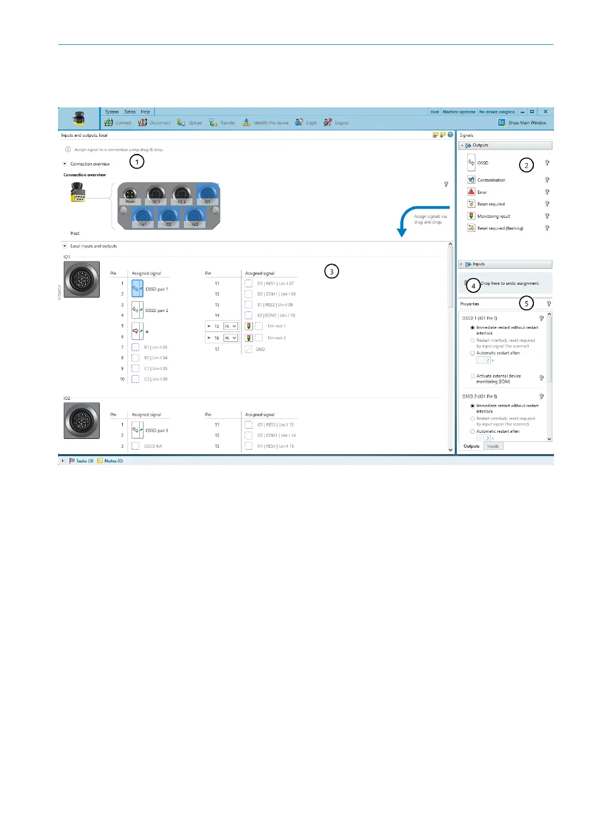
Figure 77: Inputs and outputs, local
1
Overview: Plug connectors of the safety laser scanner
2
Available signals
3
Pin assignment
4
Remove signal from connection
5
Further settings for some signals
Assign the required signals to the safety laser scanner connection in the In
puts and
outputs, local dialog box.
Connection overview
Safety Designer shows the plug connectors of the safety laser scanner.
Pin assignment
S
afety Designer displays the plug connectors with their individual pins.
Assigning signals to the pins
S
afety Designer shows the available signals on the right under Signals.
b
Click on the desired signal type (e.g., on Inputs).
The menu shows the possible inputs.
b
Drag the signal towards the pins.
CONFIGURATION 7
8025424/1ELL/2022-01-21 | SICK O P E R A T I N G I N S T R U C T I O N S | microScan3 Pro I/O
131
Subject to change without notice

Table of Contents

Other manuals for SICK microScan3 Pro I/O

Questions and Answers:

Question and Answer IconNeed help?

Do you have a question about the SICK microScan3 Pro I/O and is the answer not in the manual?

SICK microScan3 Pro I/O Specifications

General IconGeneral
Scanning angle275°
Number of fields128
Dimensions102 mm x 152 mm x 106 mm
Number of safety outputs2
Number of OSSD outputs2
Scanning range5.5 m
Protective field range5.5 m
Resolution30 mm
Number of monitoring cases128
Response time60 ms
InterfacesEthernet, USB
Operating temperature+50 °C
Protection classIP65
Supply voltage24 V DC
Storage temperature+70°C
Operating voltage24 V DC (16.8 V DC ... 28.8 V DC)
Housing materialPlastic
Connection typeMale connector

Related product manuals