Figure 54: Connection of the OSSDs of an OSSD pair
DANGER
H
azard due to lack of effectiveness of the protective device
The dangerous state may not be stopped in the event of non-compliance.
b
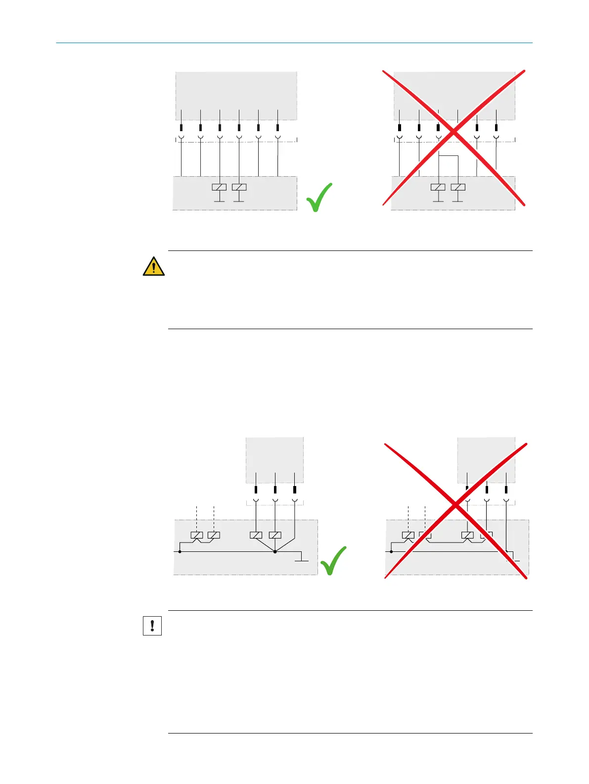
Prevent the formation of a potential difference between the load and the protec‐
tive device.
b
If y
ou connect loads to the OSSDs (safety outputs) that then also switch if con‐
trolled with negative voltage (e.g., electro-mechanical contactor without reverse
polarity protection diode), you must connect the 0 V connections of these loads
and those of the corresponding protective device individually and directly to the
same 0 V terminal strip. In the event of a fault, this is the only way to ensure that
there can be no potential difference between the 0 V connections of the loads and
those of the corresponding protective device.
Figure 55: No potential difference between load and protective device
NOTICE
Enc
losure rating IP65 only applies if the safety laser scanner is closed and the system
plug is mounted.
b
Mount the system plug and the cover plate.
b
Close each M12 plug connector on the safety laser scanner using a male cable
connector or a protective cap.
°
Tightening torque for plug connector: 0.4 Nm … 0.6 Nm.
°
Tightening torque for protective caps: 0.6 Nm … 0.7 Nm.
b
Mount the optics cover.
ELECTRICAL INSTALLATION 6
8025424/1ELL/2022-01-21 | SICK O P E R A T I N G I N S T R U C T I O N S | microScan3 Pro I/O
91
Subject to change without notice