4.3 Assembly
Important information
DANGER
H
azard due to lack of effectiveness of the protective device
Persons and parts of the body to be protected may not be recognized in case of
non-observance.
The optical beam path must not be disrupted, e.g. if the system is incorporated into
paneling.
b
Do not apply an additional front screen.
b
If a viewing slit is required, make sure that it is adequately dimensioned, see
"Dimensional drawings", page 205.
NOTE
C
ertain optical and electromagnetic ambient conditions can affect the safety laser
scanner. This may impair the machine’s availability. That is to say, the safety laser
scanner switches the machine off, although no people are located in the protective
field.
For high availability:
b
Avoid having strong electric fields in the vicinity of the safety laser scanner. These
may be caused by nearby welding or induction cables, for example.
b
Avoid condensation on the optics cover.
Prerequisites
•
T
he safety laser scanner must be affixed so that people or parts of the body are
reliably detected upon entry into the hazardous area.
•
The safety laser scanner must be affixed so that no mirrors or other exceedingly
reflective objects are in the protective field.
•
The safety laser scanner must be affixed so that no small objects (e.g. cables) are
in the protective field, even if the safety outputs do not switch to the OFF state as a
result.
•
The safety laser scanner must be affixed so that no obstacles disrupt the safety
laser scanner’s field of view. Take additional protective measures if a risk arises
due to unavoidable obstacles.
•
If people can stay between the protective device and the hazardous point without
being detected, check if additional protective measures (e.g. restart interlock) are
required.
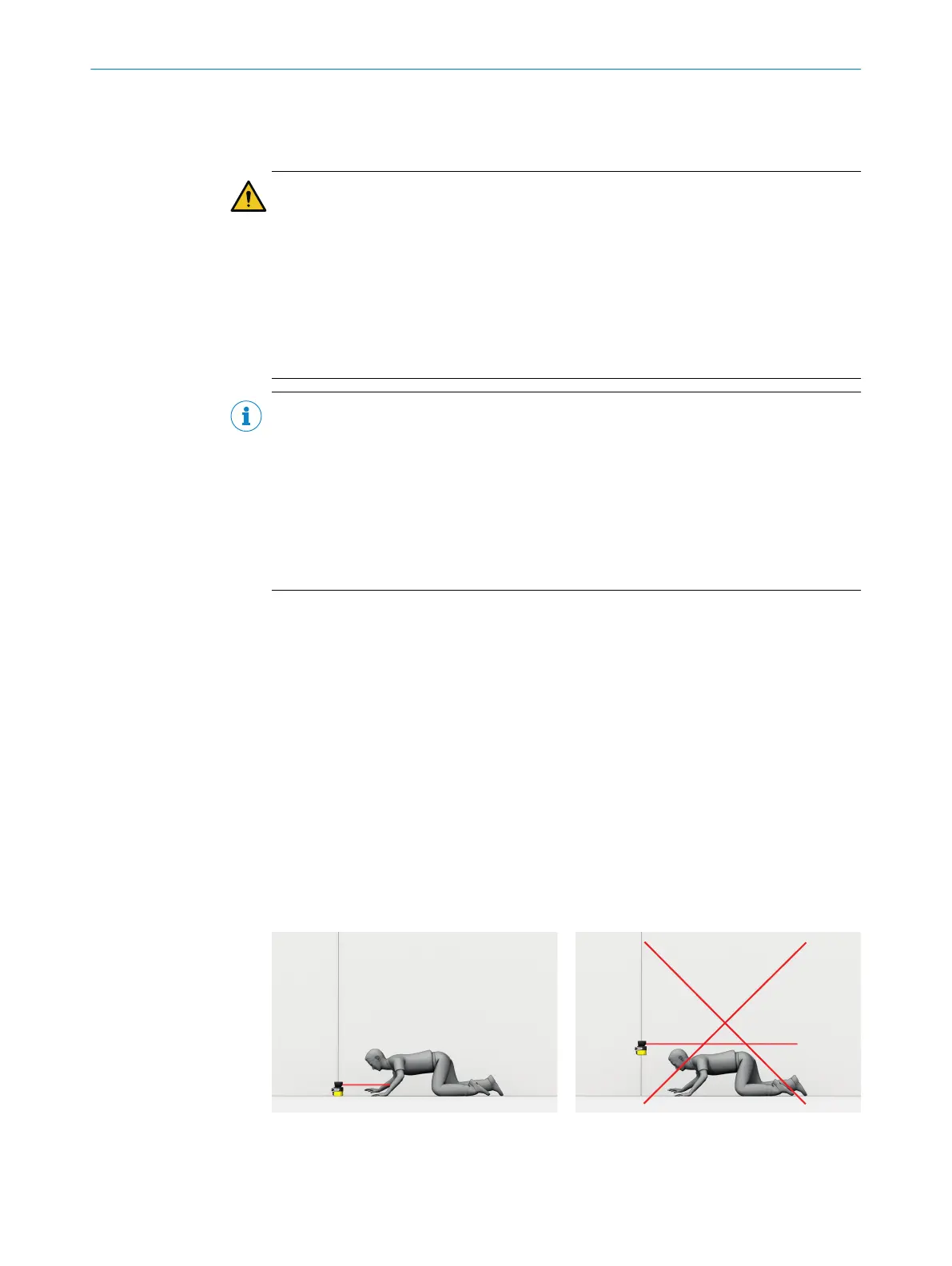
•
Reaching under, over and around, crawling beneath and stepping over the safety
laser scanner, as well as moving it, must be prevented.
Figure 17: Prevent crawling beneath
4 P
ROJECT PLANNING
26
O P E R A T I N G I N S T R U C T I O N S | microScan3 Pro I/O 8025424/1ELL/2022-01-21 | SICK
Subject to change without notice