6.2 Connection overview
NOTE
T
he USB connection may only be used temporarily and only for configuration and
diagnostics.
6.2.1 microScan3 Pro I/O
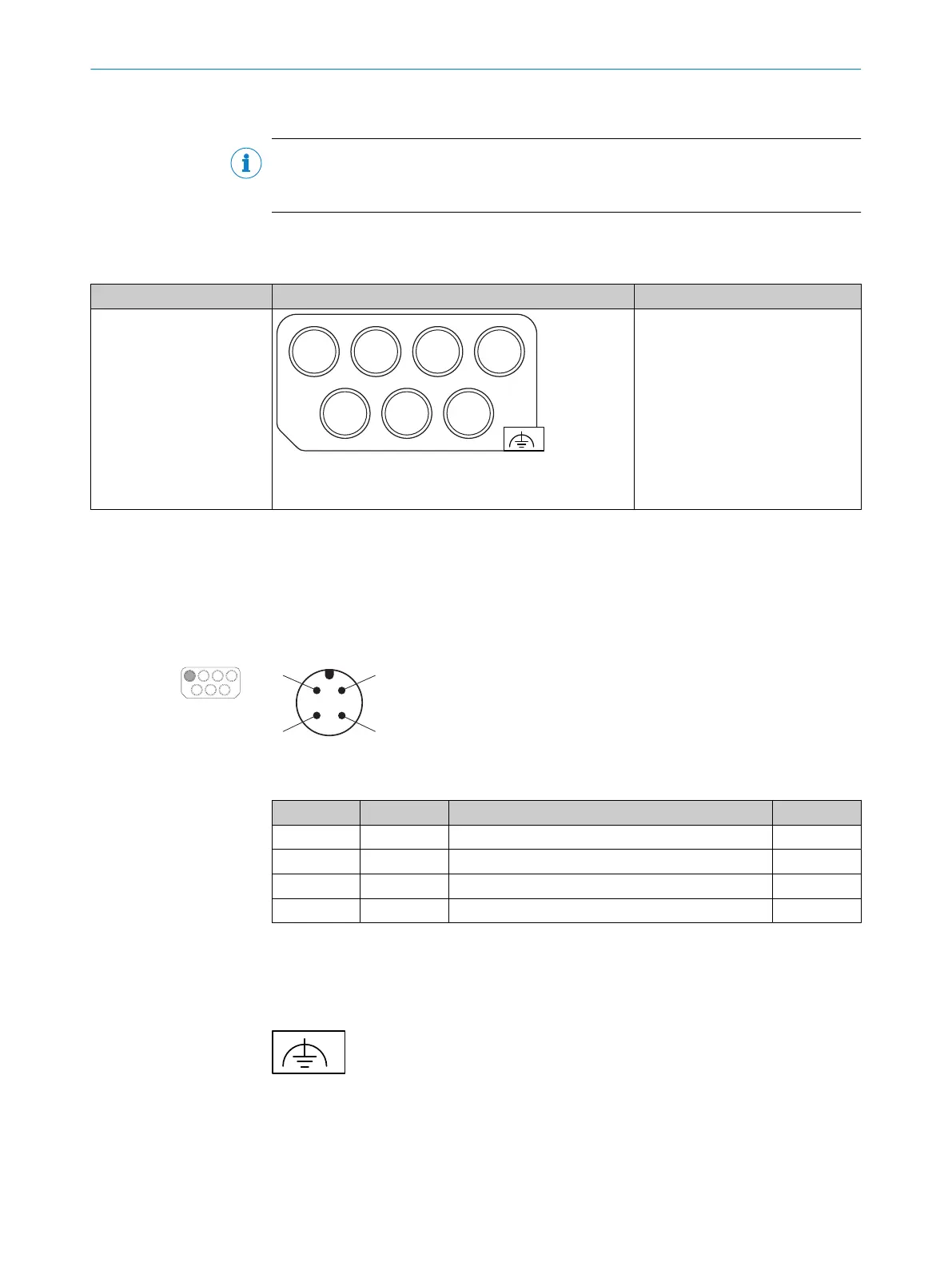
Table 6: System connector and connectors: microScan3 Pro I/O
Safety laser scanner Suitable system plug Plug connector
microScan3 Pro I/O
XD1 XF1 XF2 XG1
XG2 XG4 XG3
MICSX-CAAAMDMD1 (part number: 2115434)
•
XD1: V
oltage supply, page 92
•
XF1, XF2: 2 × Ethernet for EFI-
pro, data output, configuration
and diagnostics, page 93
•
XG1: Local inputs and outputs
1, page 93
•
XG2, XG3: Dynamic control
inputs, page 94
•
XG4: Local inputs and outputs
2, page 95
•
Alternate FE port, page 92
6.3 Pin assignment
You will find the pin assignment for the individual plug connectors in the following.
6.3.1 Voltage supply (XD1)
Voltage supply is supplied via a 4-pin, A-coding M12 male connector on the device side.
Figure 56: Pin assignment of the voltage supply (male connector, M12, 4-pin, A-coded)
Table 7: Pin assignment of the voltage supply
PIN Designation Function Wire color
1)
1 +24 V DC Supply voltage 24 V DC Brown
2 nc Not connected White
3 0 V DC Supply voltage 0 V DC
2)
Blue
4 FE Functional earth/shield Black
1)
Applies to the connecting cables recommended as accessories.
2)
All used 0 V connections of the device must be connected in the control cabinet using a low-impedance
and s
tar-point connection with 0 V DC of the power supply unit.
6.3.2 Alternative FE connection
Figure 57: Alternative FE connection
Screw connection of the alternative FE connection
•
Screw: M5 × 12
•
Tightening torque: 3.5 Nm to 5.0 Nm
6 ELECTRICAL INSTALLATION
92
O P E R A T I N G I N S T R U C T I O N S | microScan3 Pro I/O 8025424/1ELL/2022-01-21 | SICK
Subject to change without notice