EasyManuals Logo

SICK microScan3 Pro I/O User Manual

SICK microScan3 Pro I/O
228 pages
To Next Page IconTo Next Page
To Previous Page IconTo Previous Page
Page #19 background imageLoading...
Page #19 background image
Figure 7: Collision protection field, shown in purple in this document, with reference target,
pr
otective field and warning field
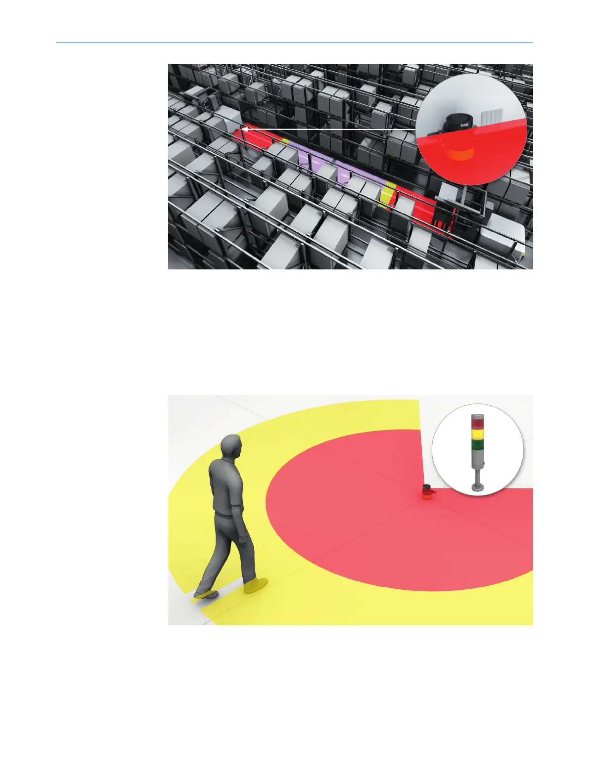
Warning field
The warning field monitors larger areas than the protective field. Simple switching
functions can be triggered with the warning field, e.g. a warning light or an acoustic
signal can be triggered if a person approaches, even before the person enters the
protective field.
The warning field must not be used for safety applications.
Figure 8: Warning field, shown in yellow or orange in this document
3.3.5 Field set
A field set consists of one or more fields. The fields in a field set are monitored
simult
aneously.
A field set can contain different field types, e.g., a protective field and a warning field.
PRODUCT DESCRIPTION 3
8025424/1ELL/2022-01-21 | SICK O P E R A T I N G I N S T R U C T I O N S | microScan3 Pro I/O
19
Subject to change without notice

Table of Contents

Other manuals for SICK microScan3 Pro I/O

Questions and Answers:

Question and Answer IconNeed help?

Do you have a question about the SICK microScan3 Pro I/O and is the answer not in the manual?

SICK microScan3 Pro I/O Specifications

General IconGeneral
Scanning angle275°
Number of fields128
Dimensions102 mm x 152 mm x 106 mm
Number of safety outputs2
Number of OSSD outputs2
Scanning range5.5 m
Protective field range5.5 m
Resolution30 mm
Number of monitoring cases128
Response time60 ms
InterfacesEthernet, USB
Operating temperature+50 °C
Protection classIP65
Supply voltage24 V DC
Storage temperature+70°C
Operating voltage24 V DC (16.8 V DC ... 28.8 V DC)
Housing materialPlastic
Connection typeMale connector

Related product manuals