Motor control
SIMOCODE pro
4-38 GWA 4NEB 631 6050-22 DS 03
Notice
Two set currents must be set for this control function:
• I
s
1 for the slow speed
• I
s
2 for the fast speed.
Depending on the current range, the current can in many cases be directly
measured at both speeds with a single current converter. Otherwise you
will need two external current converters according to the corresponding
speed (e.g. 3UF18 with a 1 A secondary transformer rated current), whose
secondary cables must lead through the current measuring module with the
range 0.3 - 3 A. The set current I
s
1 or I
s
2 must be converted according to
the secondary currents of the external transformers. For further information,
see Chapter 3.2 "Overload protection".
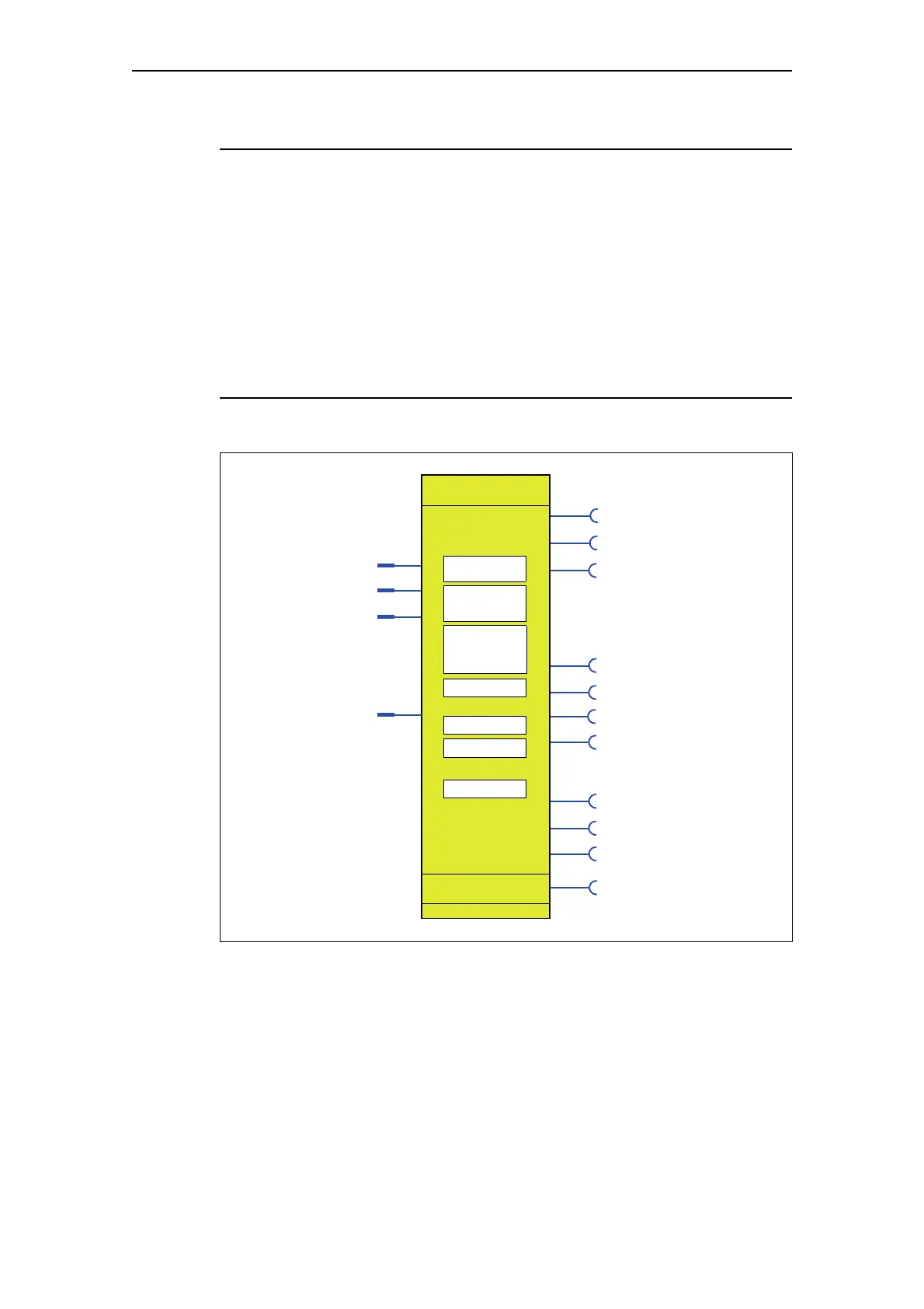
Schematic
Fig. 4-18: Schematic of the "Dahlander" control function, "Protection/Control" function block
Control commands
Auxiliary control inputs
Contactor controls
Displays
Status
QE1
QE2
FB ON*
QLA
QLE>
QLS
OFF
ON >
OFF
ON >
(ON >)
(OFF)
(Fault)
QE3
*Feedback ON
ON >>
ON >>
QLE>>
(ON >>)
Protection/Control
Non-maintained
Change-over
command Saving
Dahlander
Motor protection
Change-over pause
active
FAST
SLOW
Star contactor FAST
Extended control
Feedback time
Execution time
Load type
Change-over pause
Separate failsafe
function from
command mode
control function