System description
SIMOCODE pro
1-24 GWA 4NEB 631 6050-22 DS 03
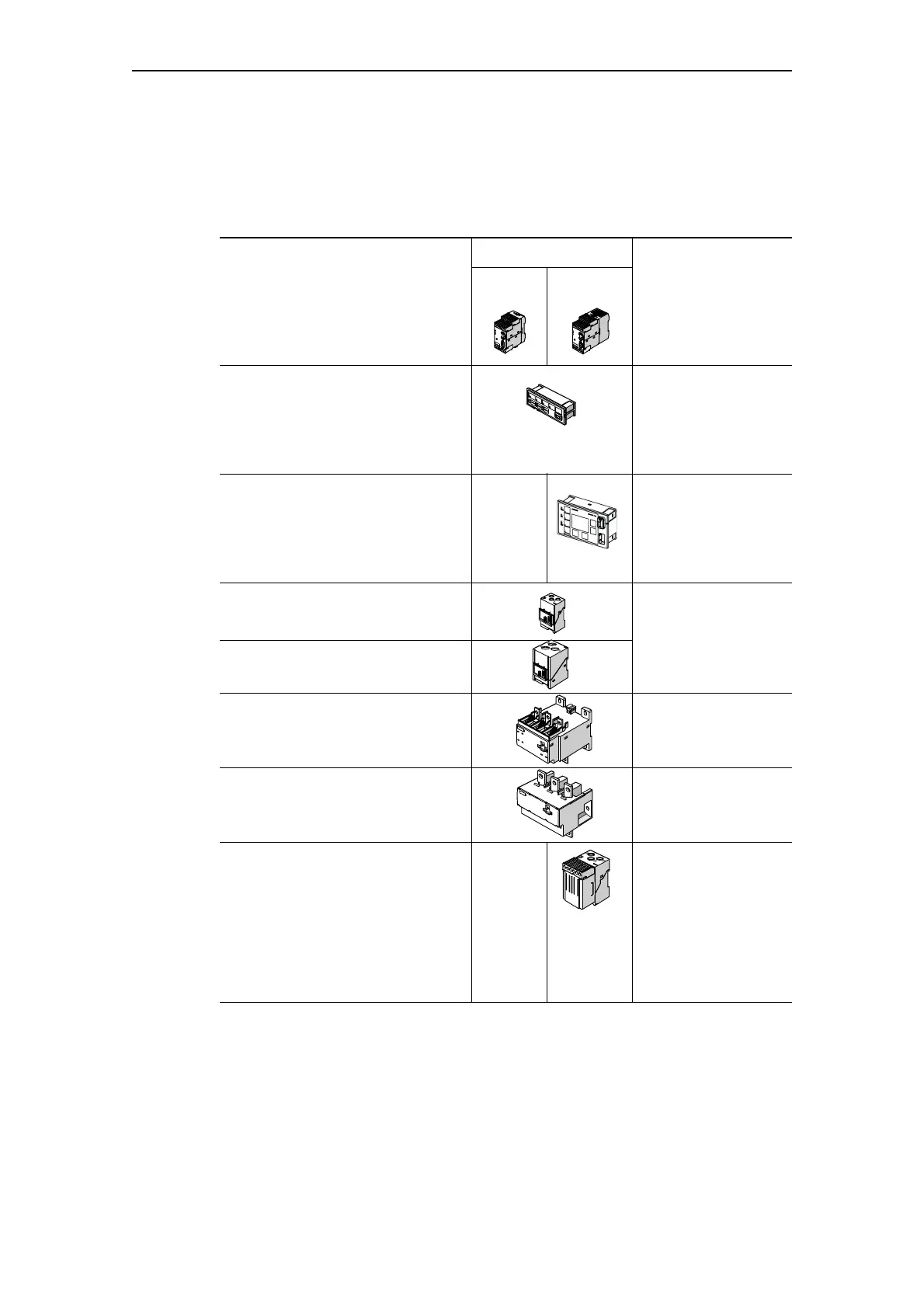
1.6 Overview of system components
Devices
SIMOCODE
Connectable
system components
pro C
(BU1)
pro V
(BU2)
Application
Operator panel (OP) Installation in the
switchgear cabinet
door. Additional control
station and display.
With system interface
for connecting a PC
Operator panel with display (OPD)
—
Installation in the
switchgear cabinet
door. Additional control
station and display.
With system interface
for PC connection
Current measuring modules (IM)
0.3 A - 3 A
2.4 A - 25 A
Current measuring
with through-hole
technology. Basic unit
can be snapped on
Current measuring module (IM)
10 A - 100 A
Current measuring module (IM)
20 A - 200 A
Current measuring
with through-hole
technology or bus
connection system
Current measuring module (IM)
63 A - 630 A
Current measuring via
bus connection system
Current/voltage measuring modules
(UM)
1)
0.3 A - 3 A
2.4 A - 25 A
—
Can only be mounted
next to the basic unit,
otherwise like current
measuring modules,
also:
- Voltage measurement
- Power measurement
- Cos phi measurement
- Phase sequence
Table 1-6: System components, devices