System description
SIMOCODE pro
GWA 4NEB 631 6050-22 DS 03
1-25
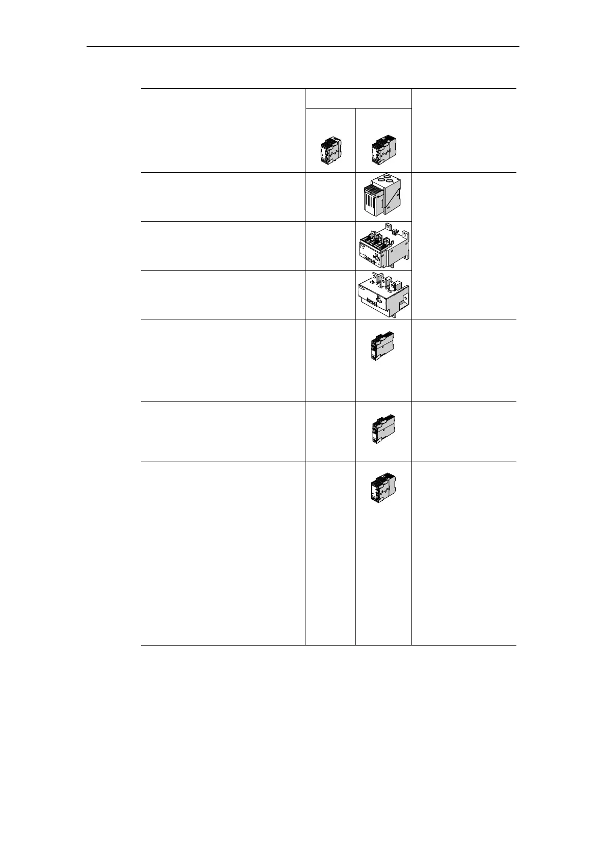
Current/voltage measuring modules
(UM)
1)
10 A - 100 A
—
Can only be mounted
next to the basic unit,
otherwise like current
measuring modules,
also:
- Voltage measurement
- Power measurement
- Cos phi measurement
- Phase sequence
Current/voltage measuring module
(UM)
1)
20 A - 200 A
—
Current/voltage measuring module
(UM)
1)
63 A - 630 A
—
Decoupling module (DCM)
—
For connection in
series upstream from a
current/voltage
measuring module at
the system interface
when used in
ungrounded networks.
Digital modules (DM)
24 V DC monostable
110 V - 240 V AC/DC monostable
24 V DC bistable
110 V - 240 V AC/DC bistable
— Additional binary inputs
and outputs. Max.
2 DM possible
Failsafe digital module
DM-F Local (DM-F Local)
—
For failsafe tripping via
hardware signal
- 2 relay enabling
circuits, wired in
parallel
- 2 relay outputs,
common ground
failsafe shutdown
- Inputs:
- 2 sensor circuits
- Start signal
- Cascade input
- Feedback circuit
- Safety function
configurable via
DIP switch
SIMOCODE
Connectable
system components
pro C
(BU1)
pro V
(BU2)
Application
Table 1-6: System components, devices (Cont.)