Safety and commissioning information for EEx areas
SIMOCODE pro
F-6 GWA 4NEB 631 6050-22 DS 03
F.2.3 Sensor circuit wiring
Caution
Lay the measuring circuit cables as separate control cables.
The use of motor feeder wires or other main current cables is not permitted.
Shielded control cables must be used if extremely inductive or capacitive
interferences are to be expected because of parallel high-voltage cables.
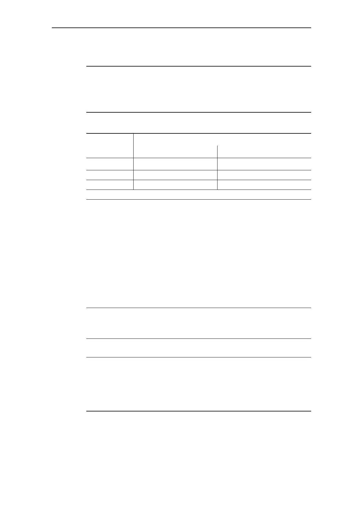
Maximum cable length of the sensor circuit cables:
Table F-2: Maximum cable length of the sensor circuit cables
We recommend evaluation of the short-circuit detection of the sensor cable.
If the short-circuit detection of the sensor cable is not evaluated, the sensor
resistance must be measured with a suitable measuring device during
commissioning or after modifications/maintenance work has been carried
out (mounting, demounting the system).
F.2.4 Short-circuit protection for type of assignment 2 according to
IEC 60947-4-1
Short-circuit protection must be carried out by separately arranged
overcurrent protection devices.
Caution
When combining with other contactors, observe the respective maximum
fuse protection of the contactor for type of assignment 2.
F.2.5 Cable protection
Caution
Avoid impermissibly high cable surface temperatures by correctly
dimensioning the cross sections!
Select a sufficient cross section - especially with heavy starting CLASS 20
to CLASS 40 (see Chapter D.7 "Short-circuit protection with fuses for motor
feeders for short-circuit currents up to 100 kA and 690 V").
Cable
cross section
Cable lengths at the thermistor input
Without short-circuit detection With short-circuit detection
1)
2.5 mm
2
2 x 2800 m 2 x 250 m
1.5 m m
2
2 x 1500 m 2 x 150 m
0.5 mm
2
2 x 500 m 2 x 50 m
1) A short circuit in the sensor circuit will be detected up to this maximum cable length.