Outputs
SIMOCODE pro
6-6 GWA 4NEB 631 6050-22 DS 03
6.3 Operator panel LEDs
Description
SIMOCODE pro has an "OP LED" function block for controlling the seven
freely-assignable LEDs. The LEDs are in the operator panel and can be used
to display any status. For this, the inputs (plugs) of the "OP LED" function
block must be connected to the respective sockets (e.g. to the sockets for
the status information of the control function).
Note
The "OP LED" function block can only be used if the operator panel (OP) is
connected and configured in the device configuration!
The "OP LED" function block consists of:
• Four plugs, "OP LED Green 1" to "OP LED Green 4", corresponding to the
green LEDs. The green LEDs are optically/constructionally allocated to the
buttons on the operator panel. They normally display feedback concerning the
motor operating state.
• Three plugs, "OP LED Yellow 1" to "OP LED Yellow 3", corresponding to the
yellow LEDs.
• Four green LEDs
• Three yellow LEDs (
not for the operator panel with display).
Overall, there is one "OP LED" function block for BU1 and BU2.
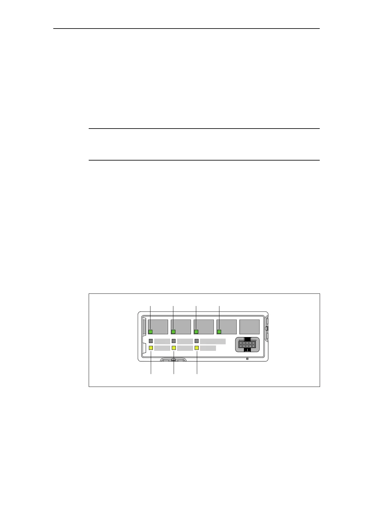
Operator panel LEDs
The following diagram shows the front view of the operator panel and the
LEDs:
Fig. 6-3: Operator panel LEDs
TEST/
RESET
DEVICE
BUS
GEN. FAULT
Green 1 Green 2 Green 3 Green 4
Yellow 1 Yellow 2 Yellow 3