Outputs
SIMOCODE pro
GWA 4NEB 631 6050-22 DS 03
6-7
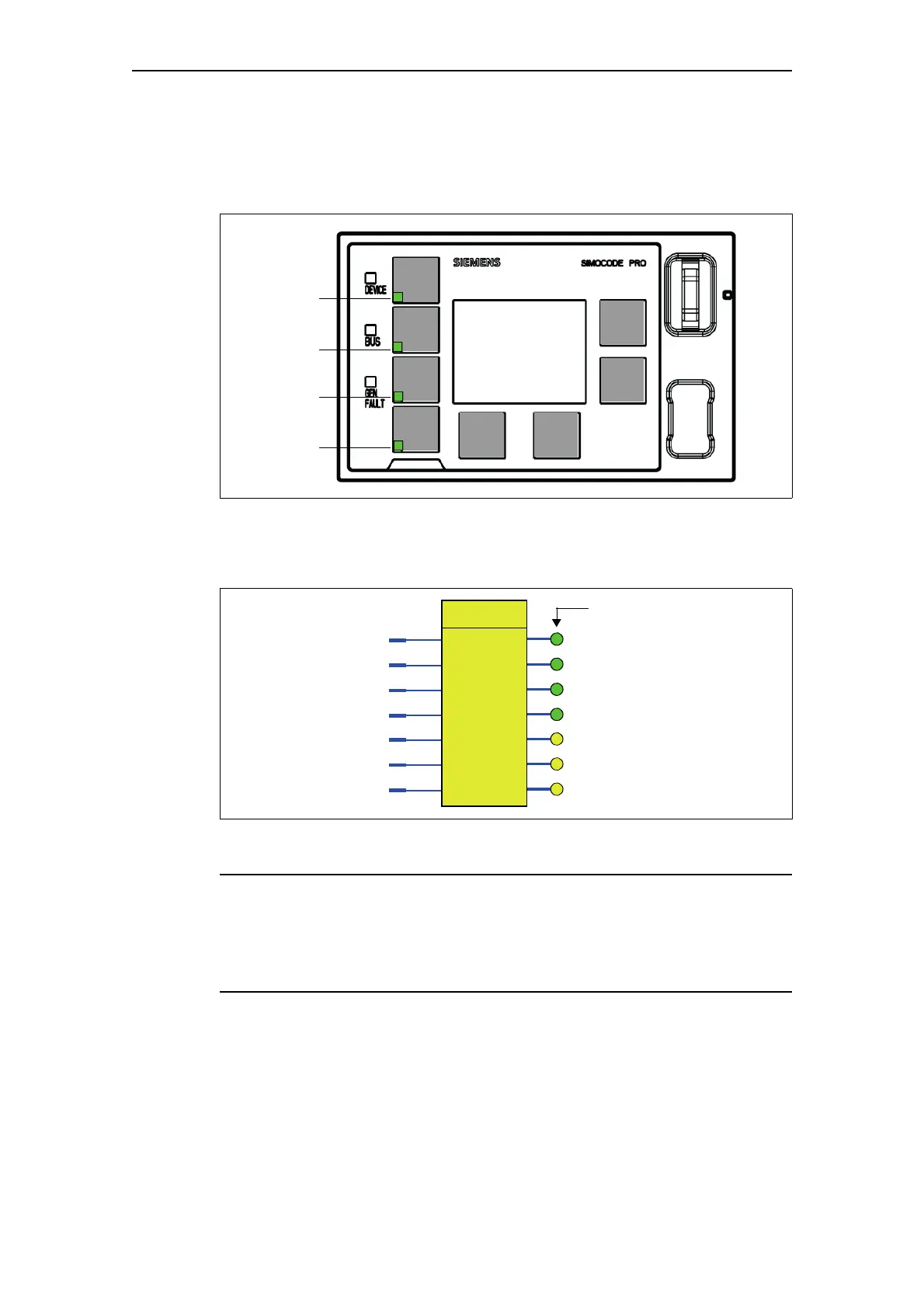
LEDs of the operator panel with display
The following diagram shows the front view of the operator panel with
display with LEDs:
Fig. 6-4: LEDs of the operator panel with display for SIMOCODE pro V
Schematic
The following schematic shows the "OP LED" function block:
Fig. 6-5: Schematic of the "OP LED" function block
Note
The three yellow LEDs mentioned in this section are not available for the
operator panel with display. Status information can be read out here directly
via the display. The corresponding three plugs can also be connected via the
software. Nevertheless, they remain ineffective.
Green 1
Green 2
Green 3
Green 4
Yellow 1
Yellow 2
Yellow 3
Green 1
Green 2
Green 3
Green 4
OP LED
LED