Inputs
SIMOCODE pro
GWA 4NEB 631 6050-22 DS 03
7-9
7.4 Digital module inputs
Description
SIMOCODE pro has two "DM Inputs" function blocks, each with 4 grouped
binary inputs with common ground potential. You can connect the buttons
for a local control station to the inputs. These signals can be further
processed in SIMOCODE pro by internally connecting the sockets of the
"DM Inputs" function blocks.
Note
The "DM Inputs" function blocks can only be used if the respective digital
module (DM) is connected and configured in the device configuration!
Note
When using the DM-F Local and DM-F PROFIsafe failsafe digital modules,
the input signals can be used as non-safety-oriented information.
Each "DM Inputs" function block consists of:
• Input terminals located on the outside of the digital module,
corresponding to the sockets "DM Input 1" to "DM Input 4"
• Sockets in SIMOCODE pro that can be connected to any plugs, e.g. to the
"Control Stations" function block.
Overall, one function block "DM1 - Inputs" and "DM2 - Inputs" for BU2.
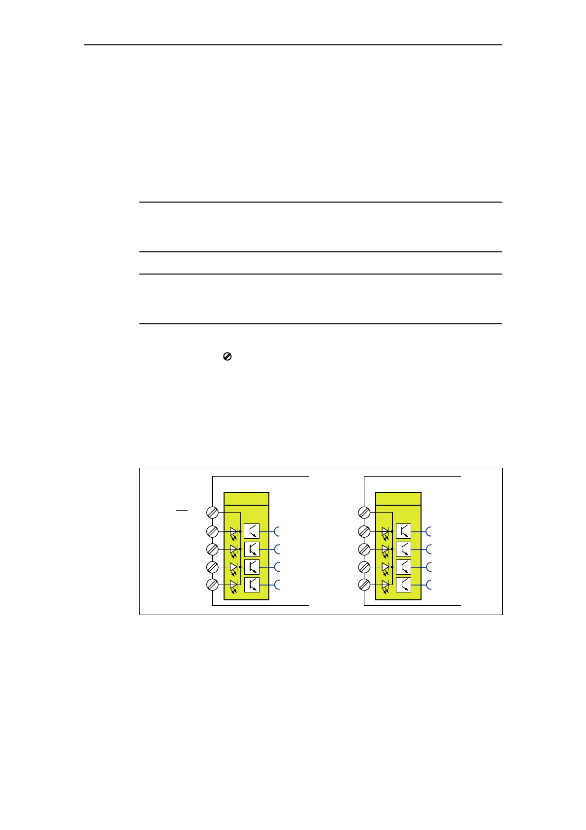
Schematic
The following schematic shows the "DM1/DM2 Inputs" function blocks:
Fig. 7-6: Schematic of the "DM1/DM2 Inputs" function blocks
Digital module (DM)
23
24
26
27
DM1 Inputs
1
2
3
4
Termina l
numbers
IN1
IN2
IN3
IN4
Digital module (DM)
23
24
26
27
DM2 Inputs
1
2
3
4
IN1
IN2
IN3
IN4
25
25