Inputs
SIMOCODE pro
7-10 GWA 4NEB 631 6050-22 DS 03
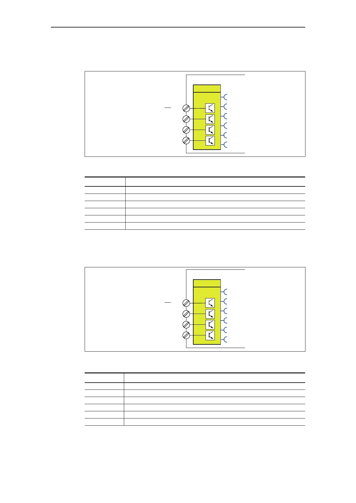
The following schematic shows the "DM1 Inputs" function block as failsafe
digital module DM-F Local:
Fig. 7-7: The following schematic shows the "DM1 Inputs" function block as failsafe digital module
DM-F Local:
Table 7-3: The following schematic shows the "DM1 Inputs" function block as failsafe digital module
DM-F Local:
The following schematic shows the "DM1 inputs" function block as failsafe
digital module DM-F PROFIsafe:
Fig. 7-8: The following schematic shows the "DM1 Inputs" function block as failsafe digital module
DM-F Local:
Table 7-4: The following schematic shows the "DM1 Inputs" function block as failsafe digital module
DM-F PROFIsafe
Input Description
Input 1 - "tripped" state
Start Start: Start input state (Y33)
Feedback Feedback: Feedback circuit state (Y34): 1 - closed; 0 - open
Cascade Cascade input state (1)
Sensor 1 Sensor circuit 1 state (Y12)
Sensor 2 Sensor circuit 2 state (Y22).
Input Description
Input 1 IN1 (83) state
Input 2 IN2 (85) state
Input 3 IN3 (89) state
Feedback FBC feedback circuit state (91): 1 - closed; 0 - open
Sensor 1 -
Sensor 2 -
Digital module (DM)
23
24
26
27
DM1 Inputs
Terminal
numbers
IN1
IN2
IN3
IN4
Input
Start
Feedback
Cascade
Sensor 1
Sensor 2
Digital module (DM)
23
24
26
27
DM1 Inputs
Terminal
numbers
IN1
IN2
IN3
IN4
Input 1
Input 2
Input 3
Feedback
Sensor 1
Sensor 2