System description
SIMOCODE pro
GWA 4NEB 631 6050-22 DS 03
1-9
1.2 Simplifying configuration with SIMOCODE pro
Conventional configuration without SIMOCODE pro
Individual components are used for control, monitoring and signal pre-
processing. The following components are to be used and the following
wiring is to be carried out:
• Insertion and wiring of overload relays, thermistor evaluation devices, current
transformers and analog/digital converters
• Wiring of the control circuit
• Connection of start/stop control devices
• The contactor must be brought into locking mode via the auxiliary switches
• Wiring of the interlocks.
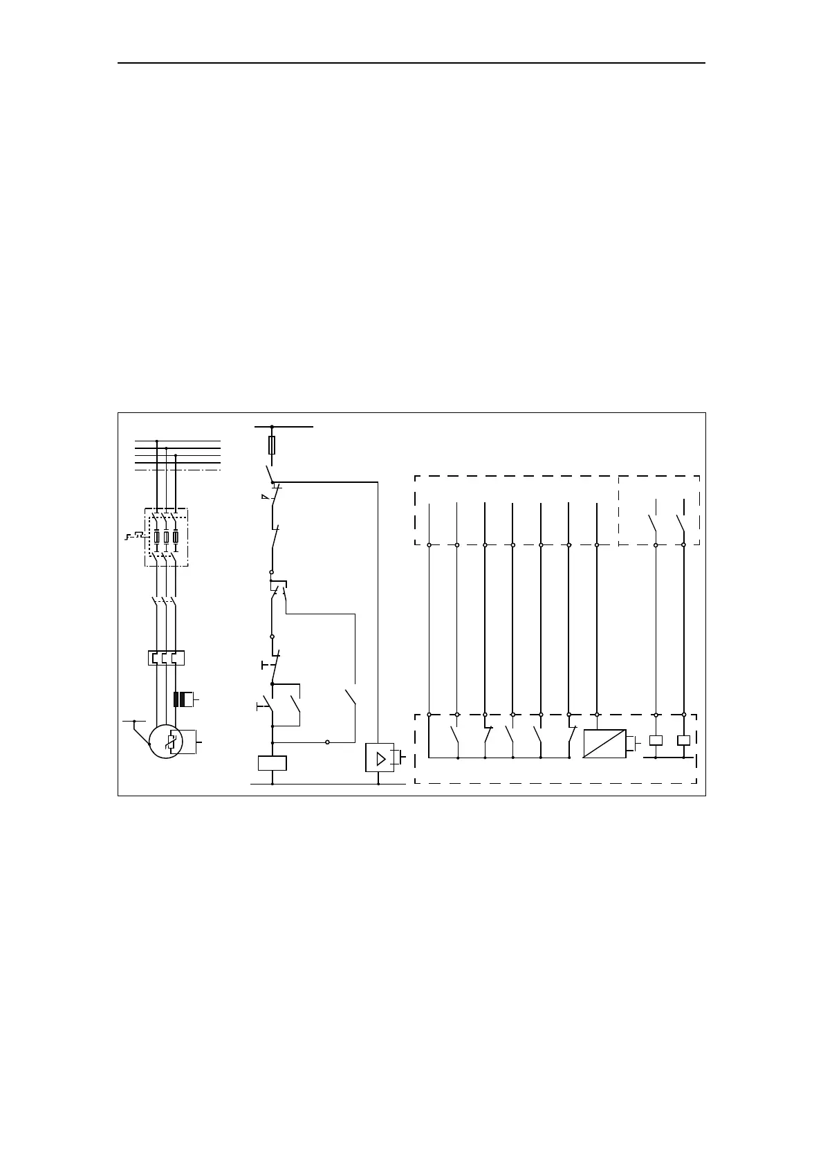
The following figure illustrates the conventional configuration of a direct
starter:
Fig. 1-3: Conventional configuration of a motor feeder (direct starter)
PLC
Start/stop
Thermistor
evaluation
Local start
Local stop
AutoManual
-Q11
1
-X3
-Q1
-Q1
S2
S1
-X2
-X1
-F3
-F2-
3/N/PE ~ 50/60 Hz 400/230 V
L1
L2
L3
N
PE
Q1
- Q1
135
246
135
246
- F2
135
246
M
3~
ϑ
1
PE
2
4 A - 20 mA
1N
2
D
A
-Q1
-Q1 -F2 -F3
Switchgear
ON
OFF
Overload
Thermistor
Automation level / I/O module
-F3
WVU
Current
-Q1 open
-Q1
N
-Q11 -Q12
Feedback Control commands
Manual/
ON/OFF
-F4
1L1
-Q1
-Q12
automatic