System description
SIMOCODE pro
1-8 GWA 4NEB 631 6050-22 DS 03
Independent operation
SIMOCODE pro C and pro V protect and control the motor feeder
independently of the automation system. Even if the automation system
(PLC) fails, or if communication is disrupted, the motor feeder remains fully
protected and controllable. SIMOCODE pro can be used without being
connected to PROFIBUS DP. This can easily be connected later, if required.
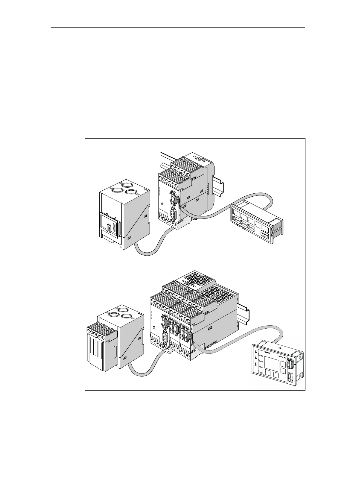
Typical configuration
The following schematic shows a typical SIMOCODE pro C and
SIMOCODE pro V hardware configuration:
Fig. 1-2: Typical SIMOCODE pro hardware configurations
System components: See Chapter 1.7 "Description of system components".
UF-01129
Current measuring
module (IM)
Basic unit (BU1)
Operator panel (OP)
SIMOCODE pro C
SIMOCODE pro V
Basic unit (BU2)
Current/voltage
measuring module (UM)
Operator panel (OPD)
Digital module (DM)
Analog module (AM)
Additional optional expansions are possible