Outputs
SIMOCODE pro
GWA 4NEB 631 6050-22 DS 03
6-15
Note (concerning examples 1 and 2):
In SIMOCODE pro, phase currents are available as a percentage of the set
current I
s
. When using the analog module output to display the effective
motor current on a connected pointer instrument, the effective motor
current is always indicated as a percentage of the set current. If the
selected control function is for a motor with only one speed, the pointer
instrument can be in percent (% of I
s
) as well as absolute (e.g. in A).
In the case of motors/control functions with two speeds and, thus, two set
currents (e.g. pole-changing starters or Dahlanders), the motor current is
only shown on the pointer instrument as a percentage of the effective set
current I
s
1 or I
s
2, depending upon which of the two speeds (slow or fast) is
prevalent.
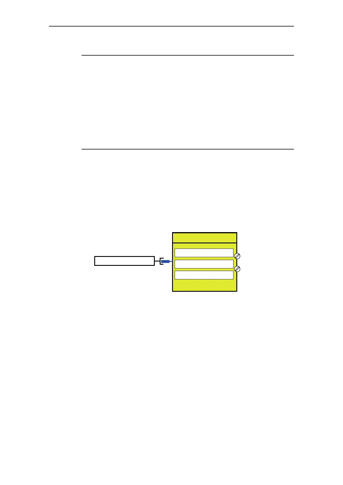
3) Output of any analog value from the automation system (cyclically
via PROFIBUS)
One word (2 bytes) can be transmitted cyclically from the automation
system to SIMOCODE pro via PROFIBUS. Any value can be output as a 0/4
to 20 mA signal by directly connecting this cyclic control word from
PROFIBUS to the analog module output. If the transmitted value is in S7
Format (0 to 27648) it must be taken into consideration when
parameterizing:
Fig. 6-12: Output of an analog value from the automation system
As a result,
– The "Start value of value range" to be selected is: 0
– The "End value of value range" to be selected is: 27648.
When the parameterized "Output signal" = 0 - 20 mA:
– 0: 0 mA at the analog module output
– 27648: 20 mA at the analog module output.
When the parameterized "Output signal" = 4 - 20 mA:
– 0: 4 mA at the analog module output
– 27648: 20 mA at the analog module output.
Cyclic Receive 2/3
Assigned
analog output value
(1 word, cycl. from the PLC)
OUT+
AM Output
OUT-
Start value of value range
End value of value range
Output signal
0
27648
0-20 mA