EasyManuals Logo

Siemens SIMOCODE pro System Manual

Siemens SIMOCODE pro
694 pages
To Next Page IconTo Next Page
To Previous Page IconTo Previous Page
Page #351 background imageLoading...
Page #351 background image
Logic modules
SIMOCODE pro
GWA 4NEB 631 6050-22 DS 03
11-9
Note
The actual value remains the same
- During parameterization or failure of the supply voltage
- If there are simultaneous input signals at input + and input –.
Note
The output is always 0 if a reset is pending.
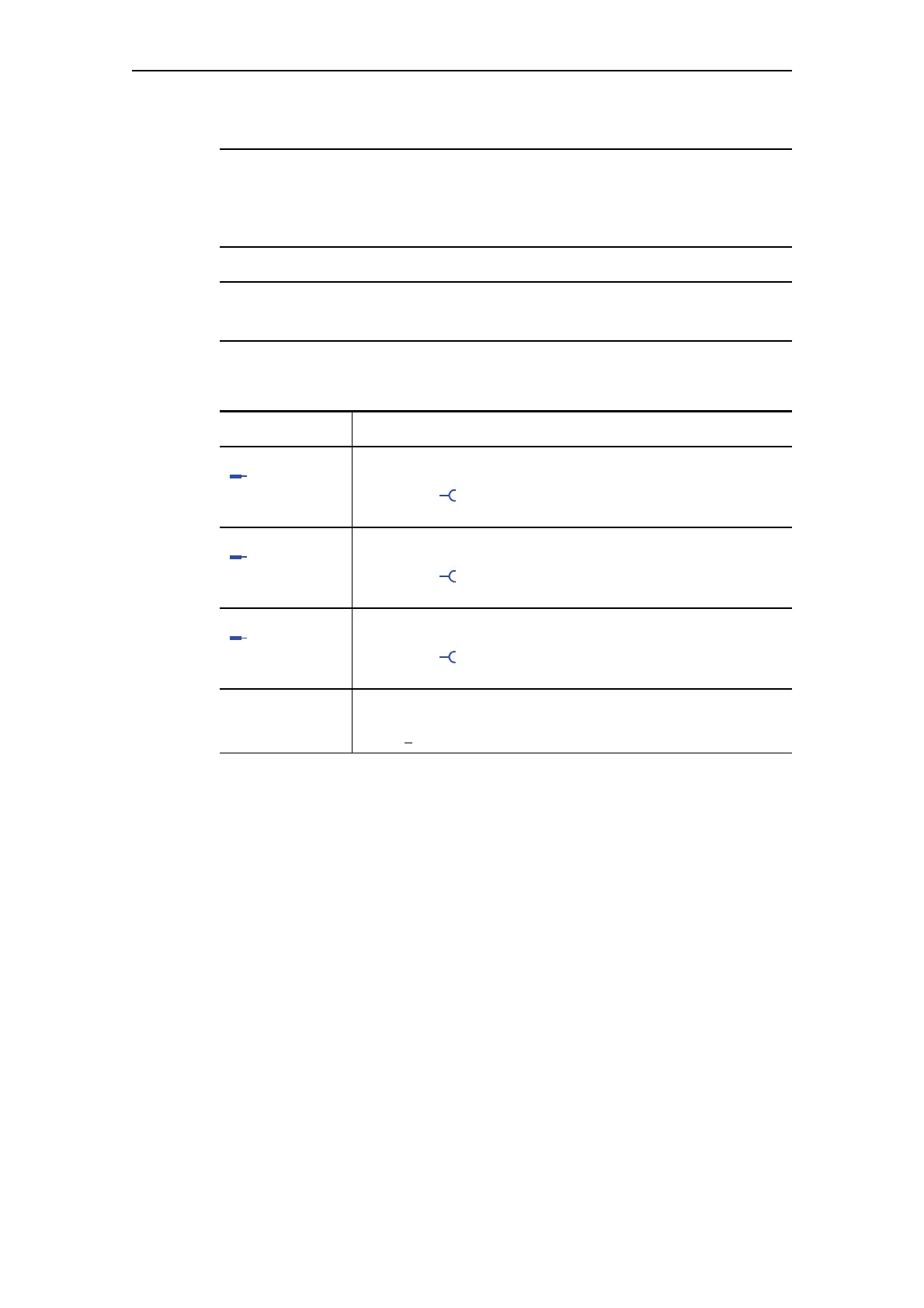
Settings
Counters 1 to 4 - Description
Input + Increases the actual value by 1.
Activation by any signal
(any sockets
e.g. device inputs, control bits from PROFIBUS DP, etc.)
Input – Decreases the actual value by 1.
Activation by any signal
(any sockets
e.g. device inputs, control bits from PROFIBUS DP, etc.)
Reset Resets the counter to 0 (count value and output)
Activation by any signal
(any sockets
e.g. device inputs, control bits from PROFIBUS DP, etc.)
Limit The maximum value that can be reached when counting and where
the counter issues an output signal.
Range: 0
- 65535
Table 11-4: Counter settings

Table of Contents

Other manuals for Siemens SIMOCODE pro

Questions and Answers:

Question and Answer IconNeed help?

Do you have a question about the Siemens SIMOCODE pro and is the answer not in the manual?

Siemens SIMOCODE pro Specifications

General IconGeneral
Protection ClassIP20
Mounting TypeDIN rail mounting
Rated Operational Voltage24 V DC
Rated CurrentUp to 820 A
Protection FunctionsOverload, short-circuit, phase failure, asymmetry, ground fault, motor stall
Operating Temperature Range-25°C to +60°C
Communication ProtocolsPROFIBUS DP, PROFINET, Modbus RTU
Analog OutputsUp to 2
Temperature MonitoringPTC/KTY, RTD (PT100/PT1000)
Digital OutputsRelay outputs, Solid-state outputs
Analog Inputs0/4-20mA, PT100/PT1000

Related product manuals