3
05.01
3.5 Overview, position sensing
3-70
Siemens AG 2001 All rights reserved
SIMODRIVE 611 Planning Guide (PJU) – 05.01 Edition
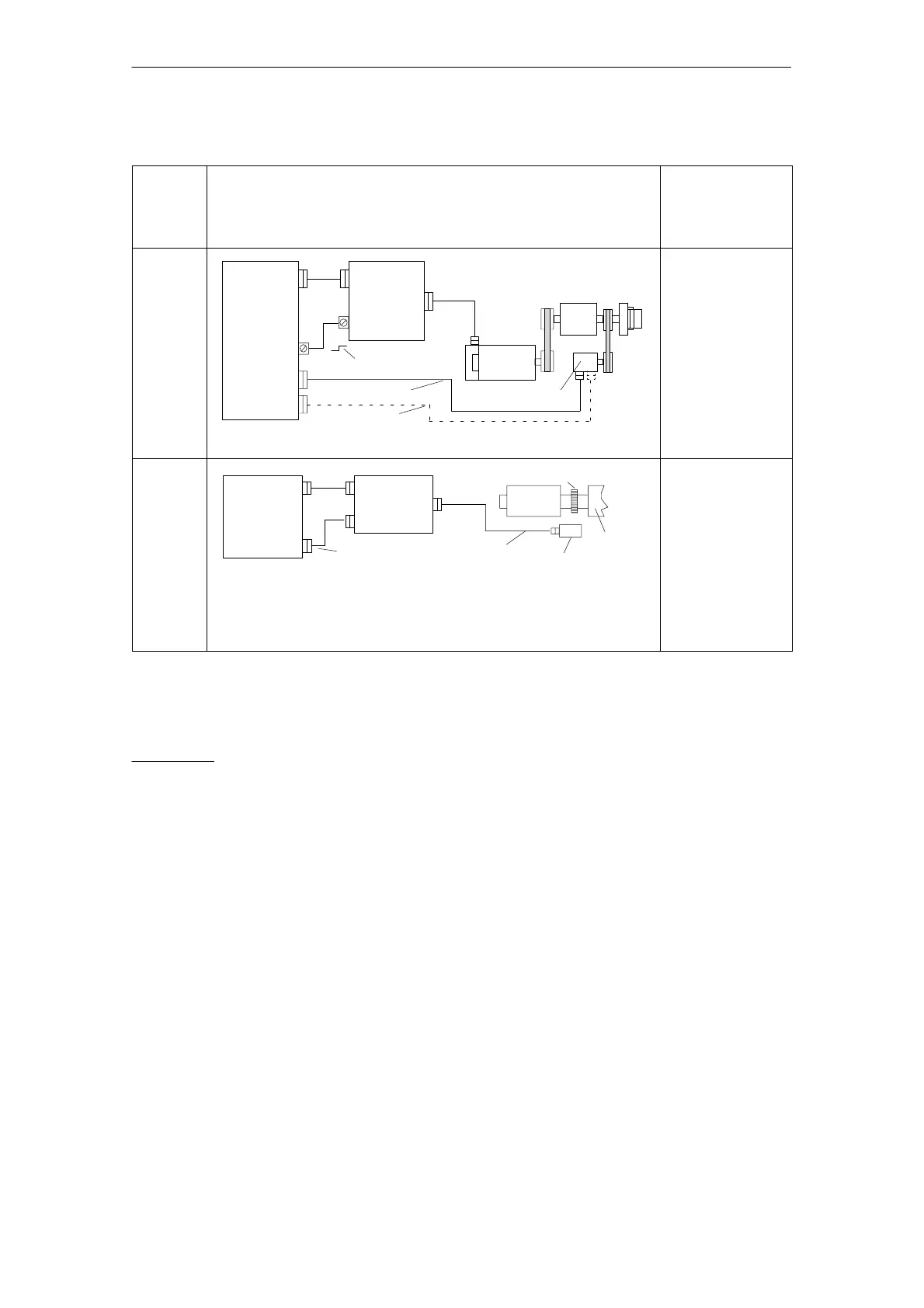
Table 3-4 Direct position sensing, analog controls
Control
board
version
Direct position sensing, analog controls
M: Max. possible
measuring steps
G: Encoder system
accuracy
Z: Pulse number
Main
spindle
control
with
analog
setpoint
inter–
face
C–axis operation with NC
Numerical
control
SIMODRIVE
drive
module
(analog)
Standard/C–axis operation
n*
1PH4/6/7
Spindle encoder
Standard track
C–axis track
l 50 m
M and G are
dependent on the
accuracy of the
optional encoder
system and the
evaluation technique
in the NC
Main
spindle
control
with
analog
setpoint
inter–
face
WSG
output
for NC
Numerical
control
SIMODRIVE
drive
module
(analog)
Spindle positioning with the NC
WSG interface
n*
Incremental
Toothed–wheel (measuring wheel)
1PH2
Spindle
Sensing head
l 50 m
M = 2048 ⋅ Z
per 360 degrees
mech.
G depends on the
precision of the
toothed/measuring
wheel encoder
system
Condition: Z = 2
n
1) The absolute accuracy when synchronizing with a BERO is a function of:
– the BERO switching time
– BERO hysteresis
– signal edge gradient of the BERO signal (dependent on the direction of rotation!) and the switching thresholds
in the drive; high >13 V, low < 5 V
– the search speed or the signal run times in the evaluation electronics
2) Distance–coded reference marks can be evaluated
3 Motor Selection, Position/Speed Sensing

 Loading...


