3
05.01
3.5 Overview, position sensing
3-71
Siemens AG 2001 All rights reserved
SIMODRIVE 611 Planning Guide (PJU) – 05.01 Edition
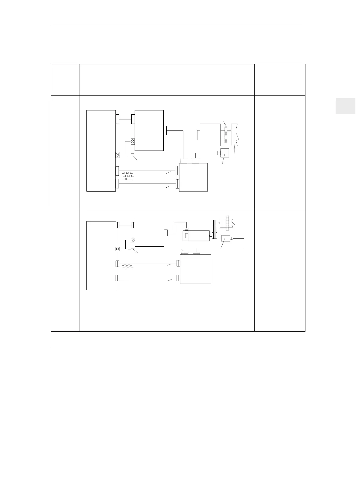
Table 3-4 Direct position sensing, analog controls
Control
board
version
Direct position sensing, analog controls
M: Max. possible
measuring steps
G: Encoder system
accuracy
Z: Pulse number
Main
spindle
control
with
analog
setpoint
inter–
face
Numerical
control
SIMODRIVE
drive
module
(analog)
Standard/C–axis operation
n*
l < 50 m
Standard track
C–axis track
Incremental
Toothed wheel
1PH2
Spindle
Sensing head
L1
L2
L1 and L2 50 m
ks
HGL module
kc
C–axis operation with NC
x4
x4
HGL module: refer to Section 3.6
Ms = ks ⋅ Z ⋅ 4
per 360 degrees
mech.
G depends on the
precision of the
toothed/measuring
wheel encoder
system
Standard track
C–axis track
Mc = kc ⋅ Z ⋅ 4
per 360 degrees
mech.
ks...1, 2, 4, 8
kc...175.78, 351.56
ks, kc...
factors which can
be set in the HGL
module
Main
spindle
control
with
analog
setpoint
inter–
face
Numerical
control
SIMODRIVE
drive
module
(analog)
Standard/C–axis operation
n*
Standard track
C–axis track
Toothed wheel
Sensing head
ks
HGL module
kc
Spindle positioning with the NC
x4
x4
HGL module: refer to Section 3.6
1PH4/6/7
Terminating connector
l 50 m
l 50 m
l 50 m
Mc = kc ⋅ Z ⋅ 4
per 360 degrees
mech.
Ms = ks ⋅ Z ⋅ 4
per 360 degrees
mech.
Standard track
C–axis track
ks...1, 2, 4, 8
kc...175.78, 351.56
ks, kc...
factors which can be
set in the HGL
module
G depends on
the precision of
the toothed/
measuring wheel
encoder system
1) The absolute accuracy when synchronizing with a BERO is a function of:
– the BERO switching time
– BERO hysteresis
– signal edge gradient of the BERO signal (dependent on the direction of rotation!) and the switching thresholds
in the drive; high >13 V, low < 5 V
– the search speed or the signal run times in the evaluation electronics
2) Distance–coded reference marks can be evaluated
3 Motor Selection, Position/Speed Sensing

 Loading...


