3
05.01
3.5 Overview, position sensing
3-72
Siemens AG 2001 All rights reserved
SIMODRIVE 611 Planning Guide (PJU) – 05.01 Edition
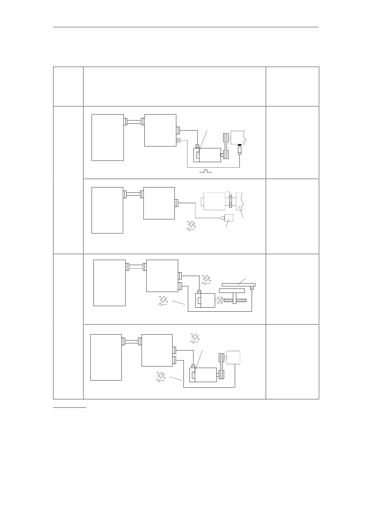
Table 3-5 Direct position sensing, digital controls
Control
board
version
Direct position sensing, digital controls
M: max. possible
measuring steps
G: Encoder system
accuracy
V: Multiplication
Z: Pulse number
Drive
control
Perfor–
mance
digital
Numerical
control
SIMODRIVE
drive
module
(digital)
Spindle positioning with the NC
n*
1PH4/6/7
Incremental
BERO
BERO function for feed
drives not released
l 50 m
M = V*Z
per 360 degrees
mech.
V = 2048
G
Motor
encoder
=
0.006 degrees
G
BERO
=
1)
FD and
MSD
Basic
version
SIMODRIVE
drive
module
Spindle positioning with the NC
n*
Toothed wheel
1PH2
Spindle
Sensing head
SINUMERIK
with digital
coupling
(digital)
l 50 m
Voltage signals
M = V*Z
per 360 degrees
mech.
G depends on the
precision of the
toothed/measuring
wheel encoder
system
Drive
control
Perfor–
mance
Digital
FD and
SIMODRIVE
drive
module
Positioning with NC
n*
1FT6
Linear
2)
measuring
system,
incremental
SINUMERIK
with digital
coupling
(digital)
l 50 m
Current signals
l 18 m
1FK6
Voltage
signals
M = 2048 per
encoder signal
period and grid
division
G is dependent on
the accuracy of the
optional encoder
system.
MSD
with addi–
tional
input,
current signa
Spindle positioning with the NC
Numerical
control
SIMODRIVE
drive
module
(digital)
n*
1PH4/6/7
Incremental
Rotary measuring
system, incremental
l 50 m
l 18 m
Current signals
Voltage
signals
M = V*Z
per 360 degrees
mech.
V = 2048
G is dependent on
the accuracy of the
optional encoder
system.
1) The absolute accuracy when synchronizing with a BERO is a function of:
– the BERO switching time
– BERO hysteresis
– signal edge gradient of the BERO signal (dependent on the direction of rotation!) and the switching thresholds
in the drive; high >13 V, low < 5 V
– the search speed or the signal run times in the evaluation electronics
2) Distance–coded reference marks can be evaluated
3 Motor Selection, Position/Speed Sensing

 Loading...


